derekcohen
Member
- Joined
- Jun 22, 2008
- Messages
- 922
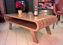
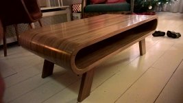
My nephew is getting married in February, and I offered to make a piece of furniture as a gift. The offer was open-ended, and the couple decided they wanted a coffee table. Their taste runs to mid century Danish, and so I sent them a bunch of example from the Internet to get the ball rolling. They fell in love with the following design ...
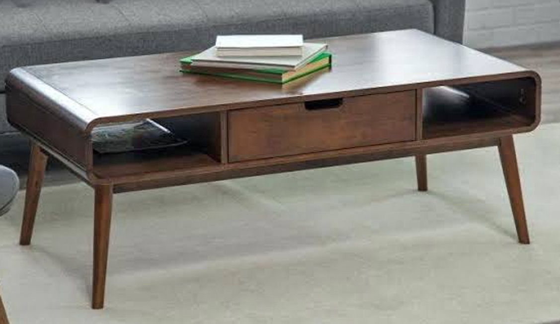
There shall be a few interesting challenges along the way since I am using solid wood and, I imagine, the "model" is built of veneered ply.
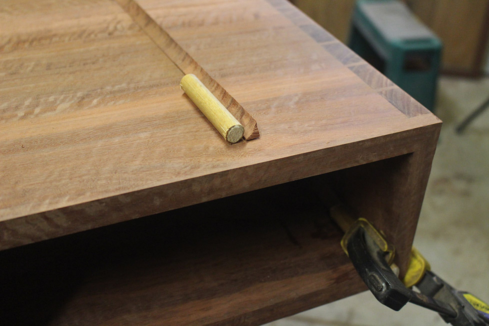
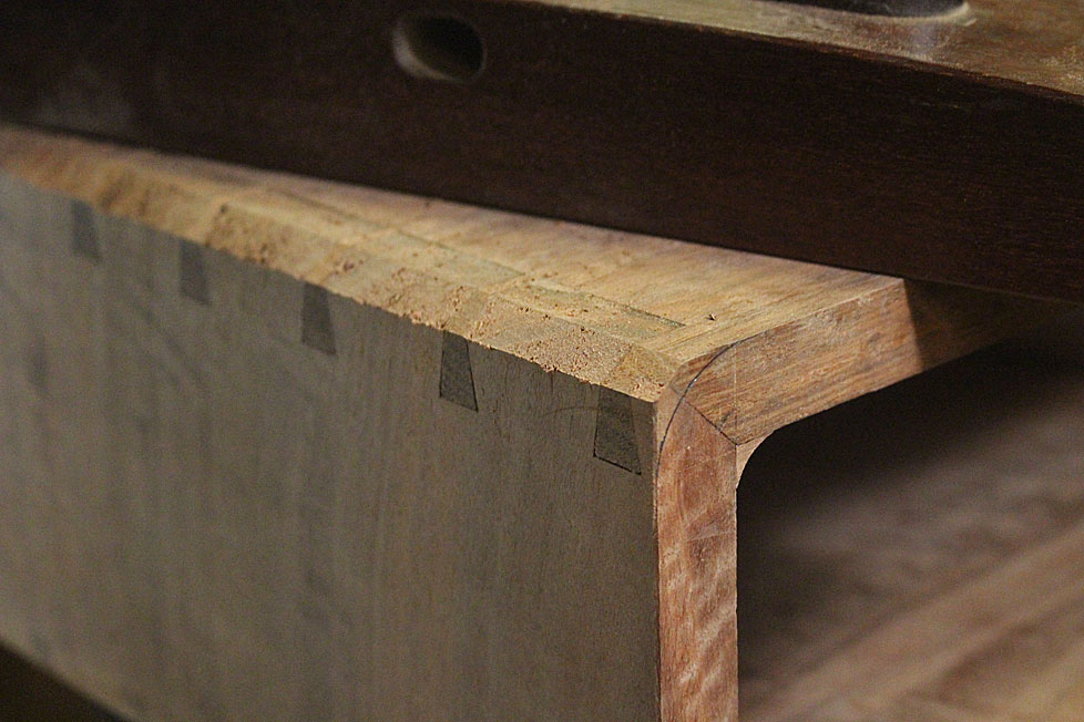
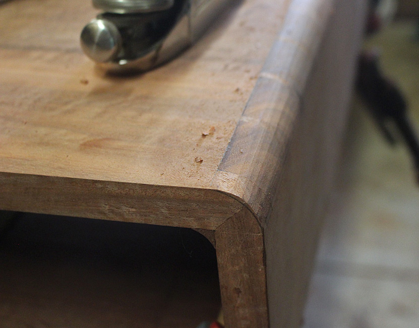
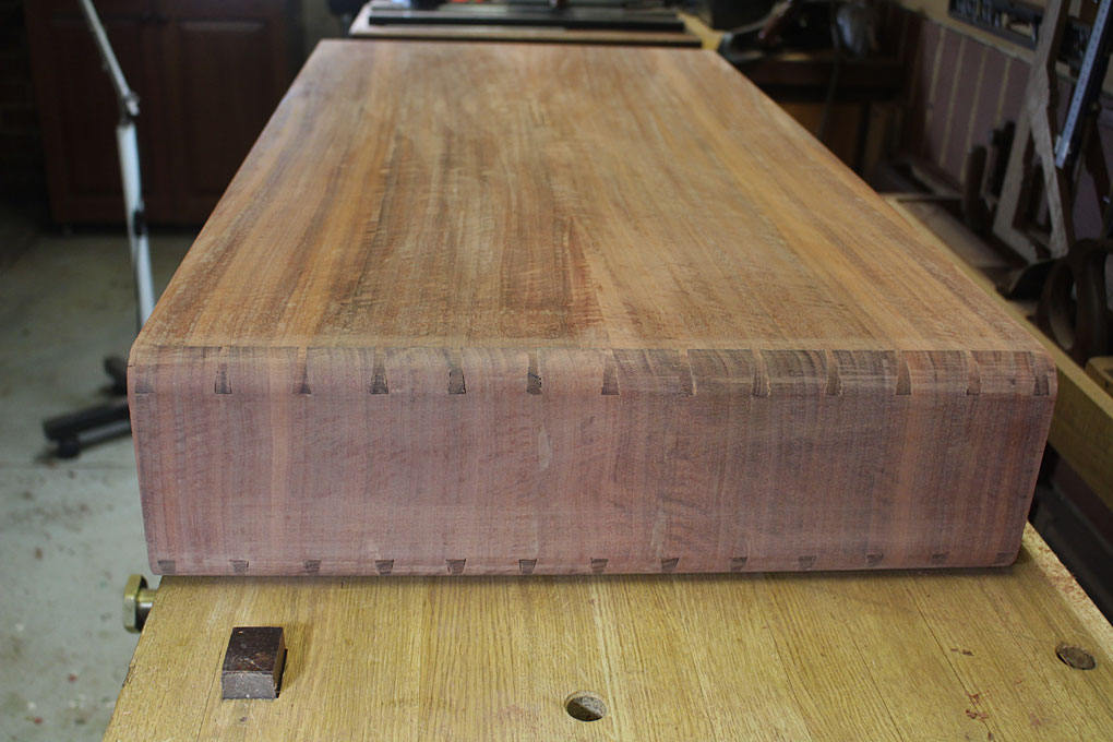
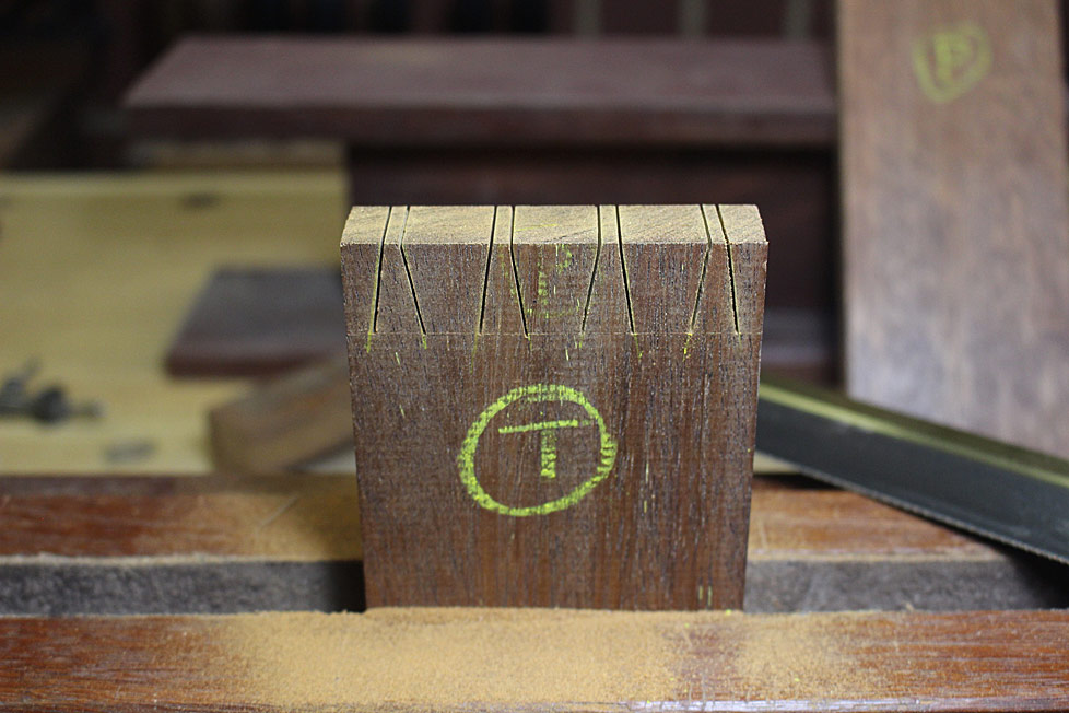
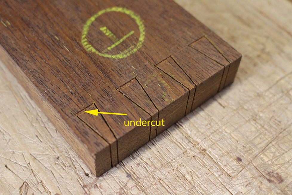
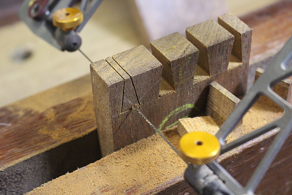
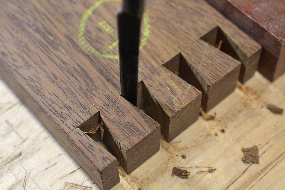
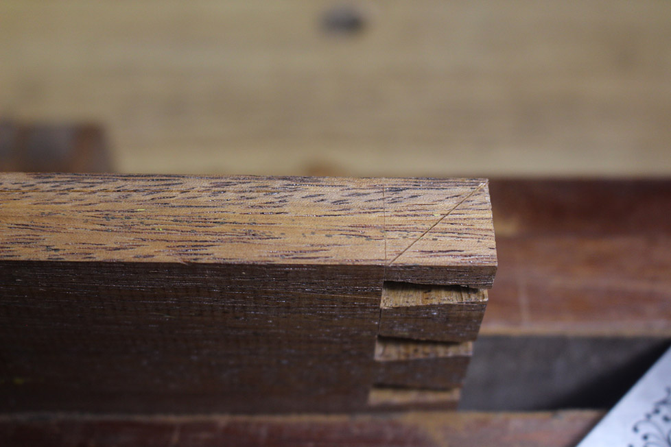
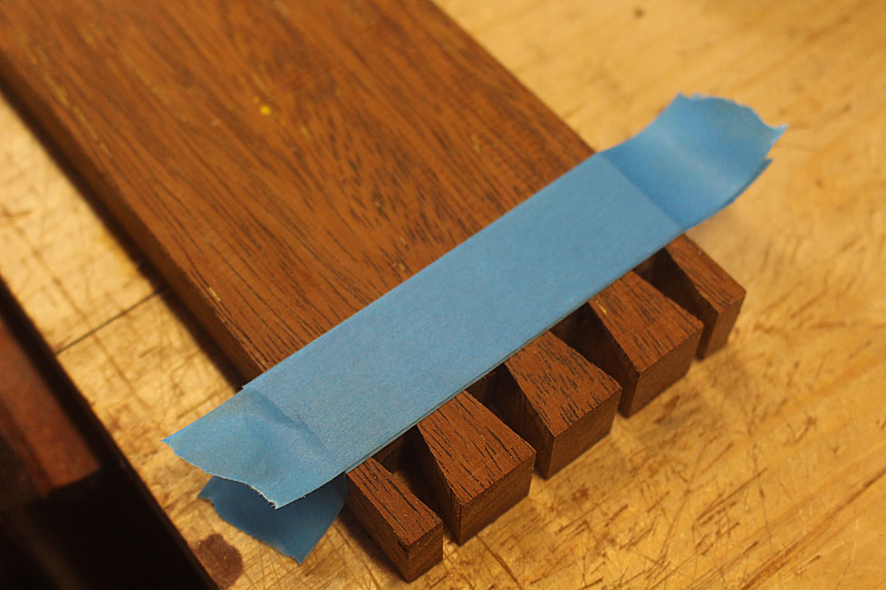
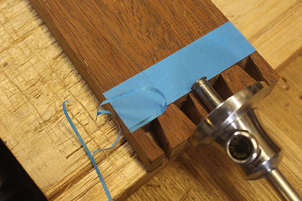
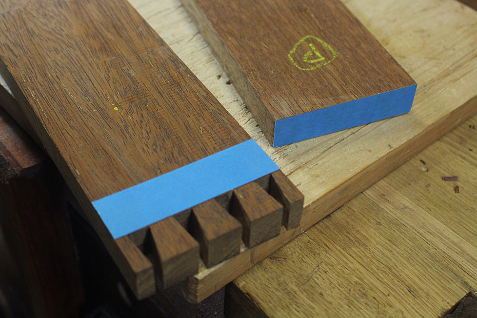
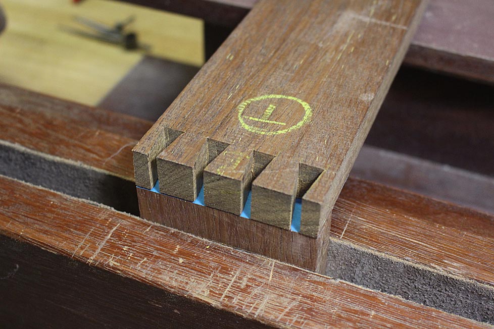
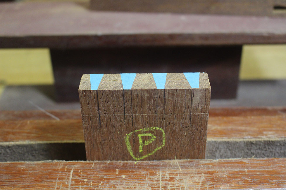
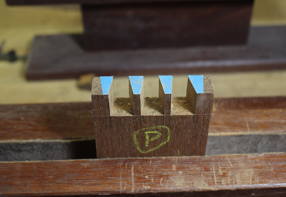
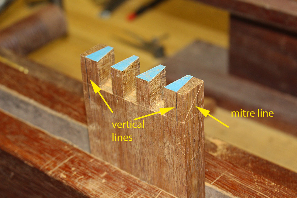
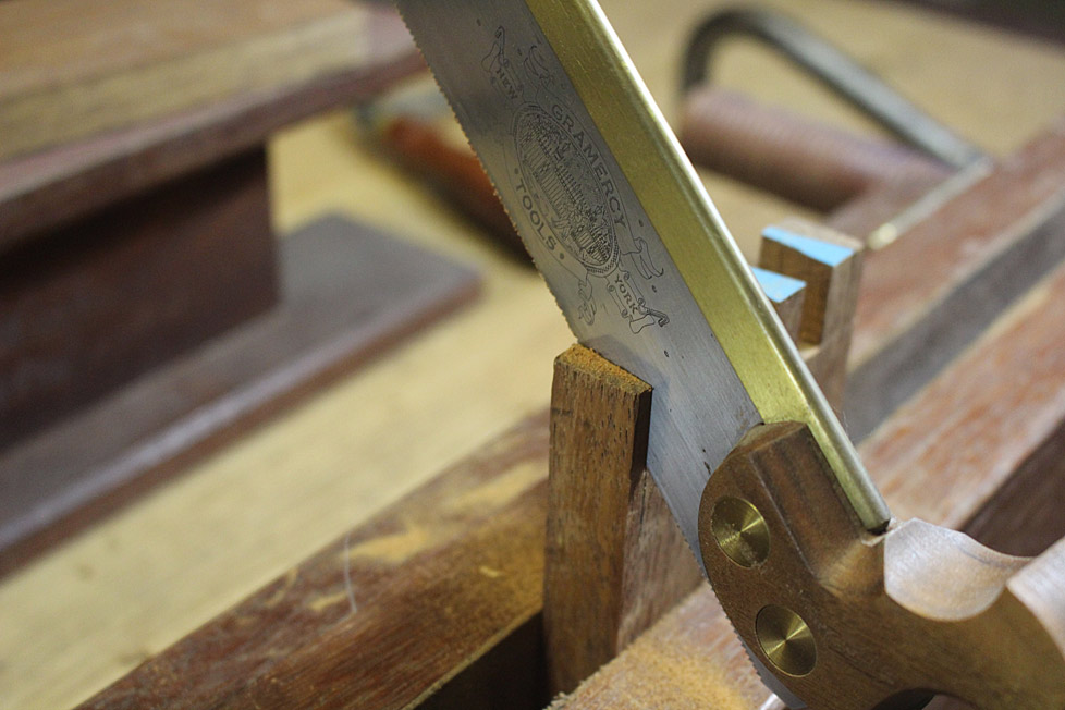
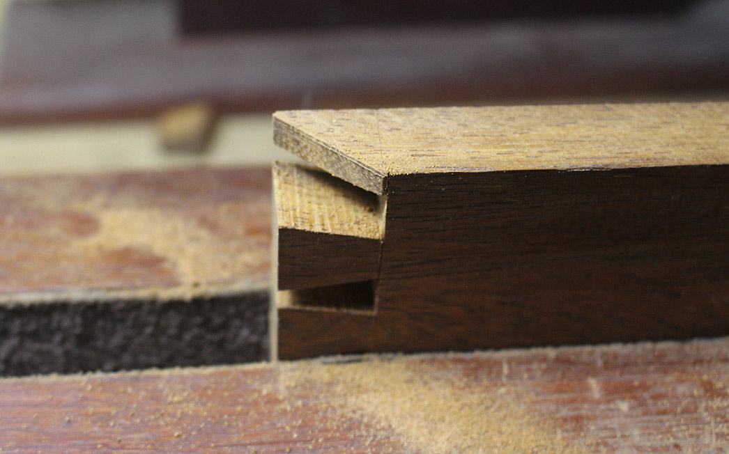
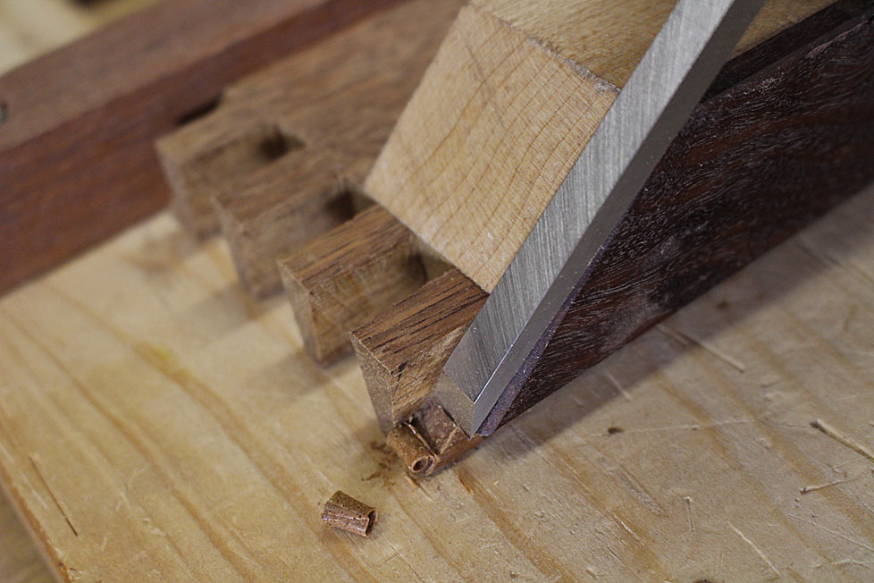
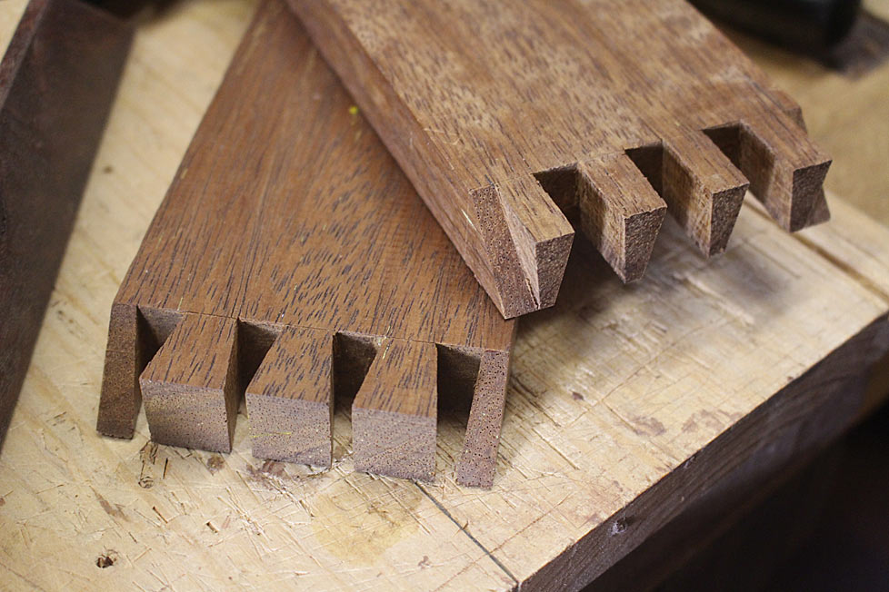
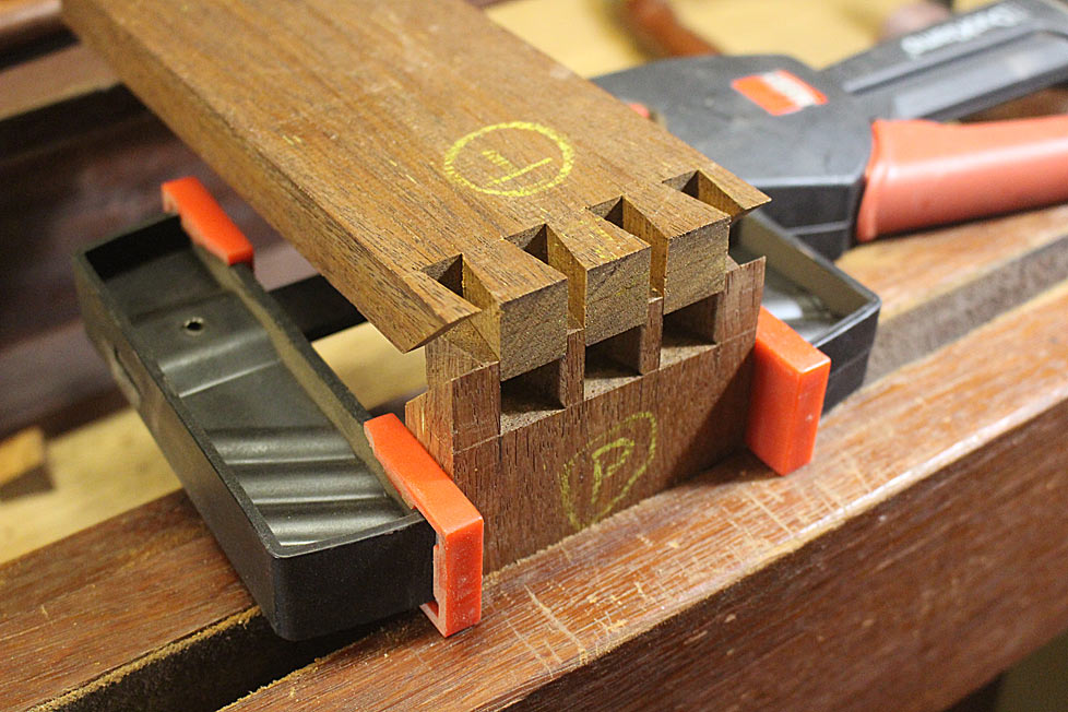
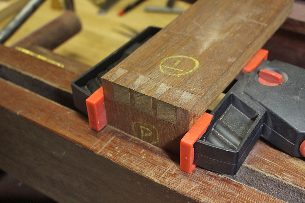
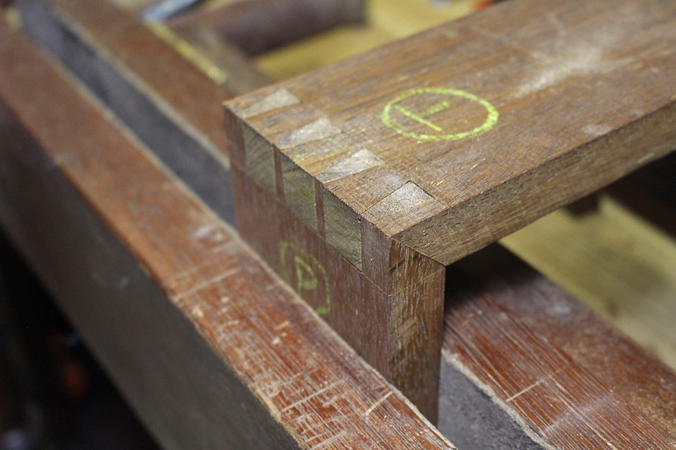
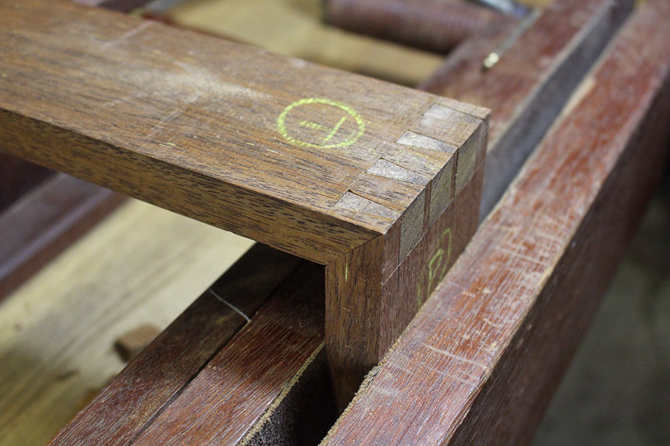
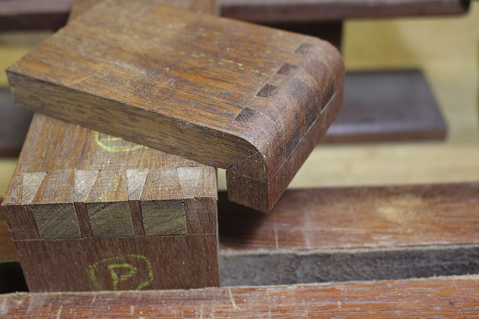
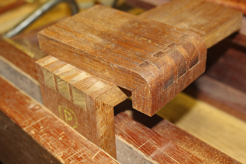
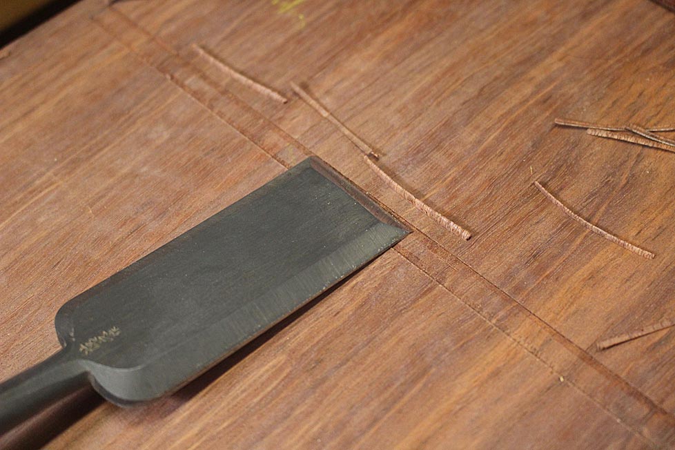
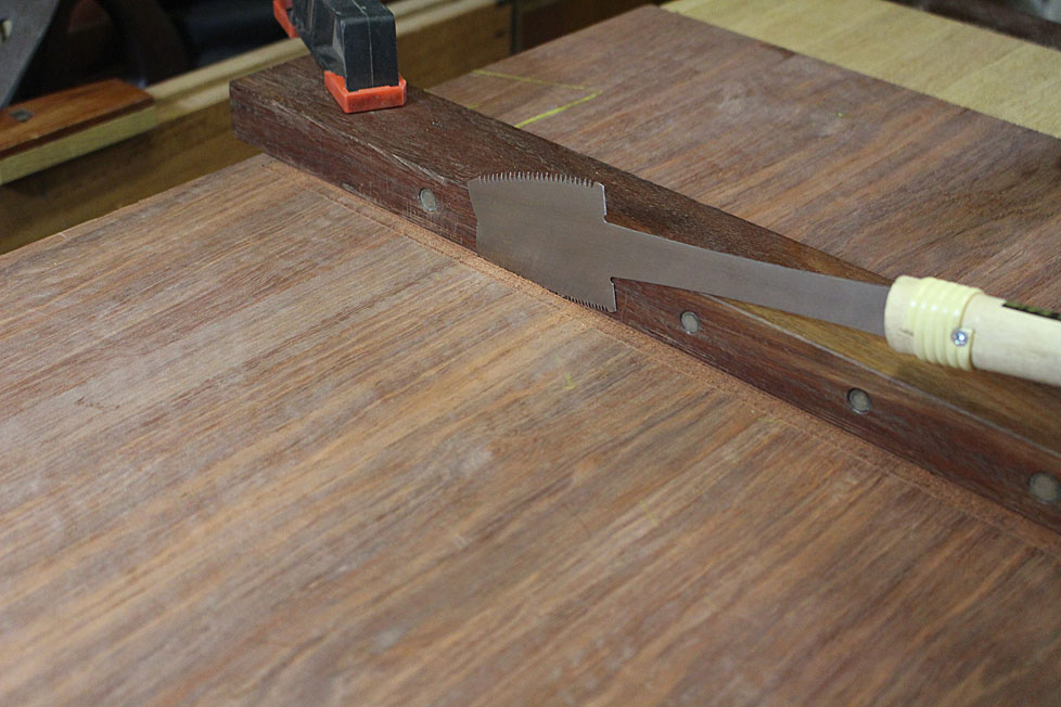
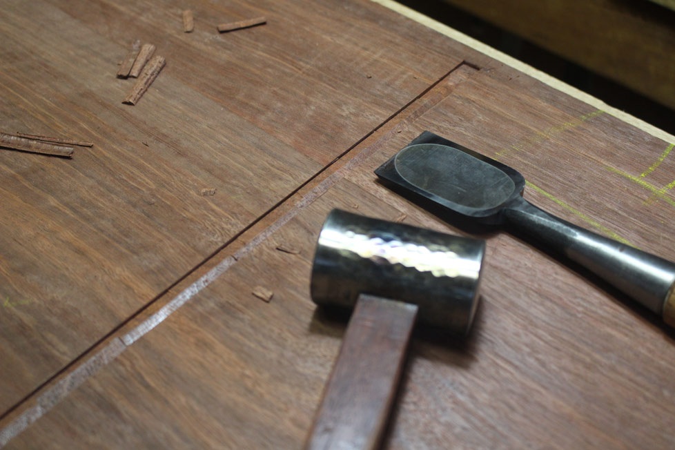
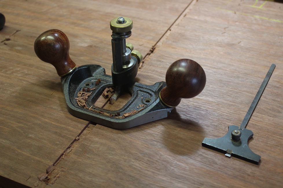
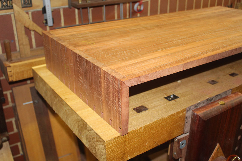
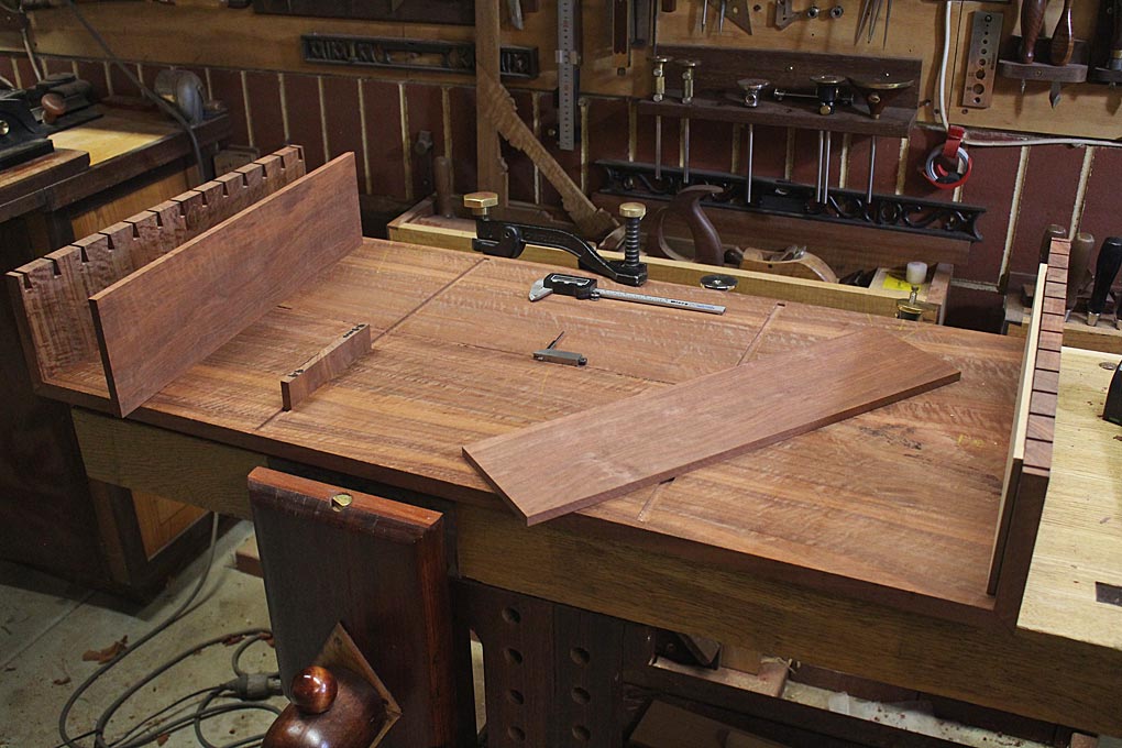
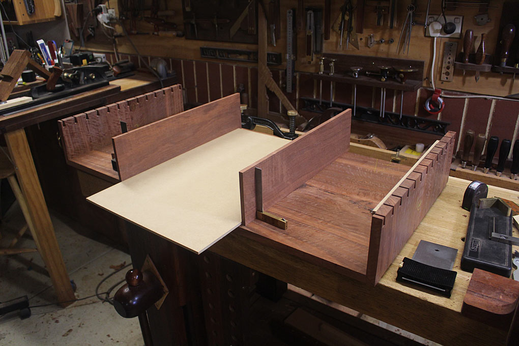
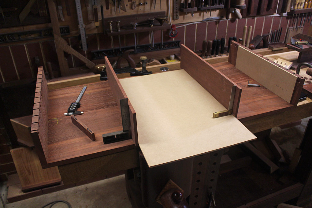
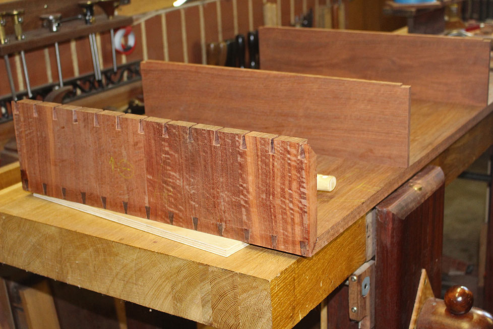
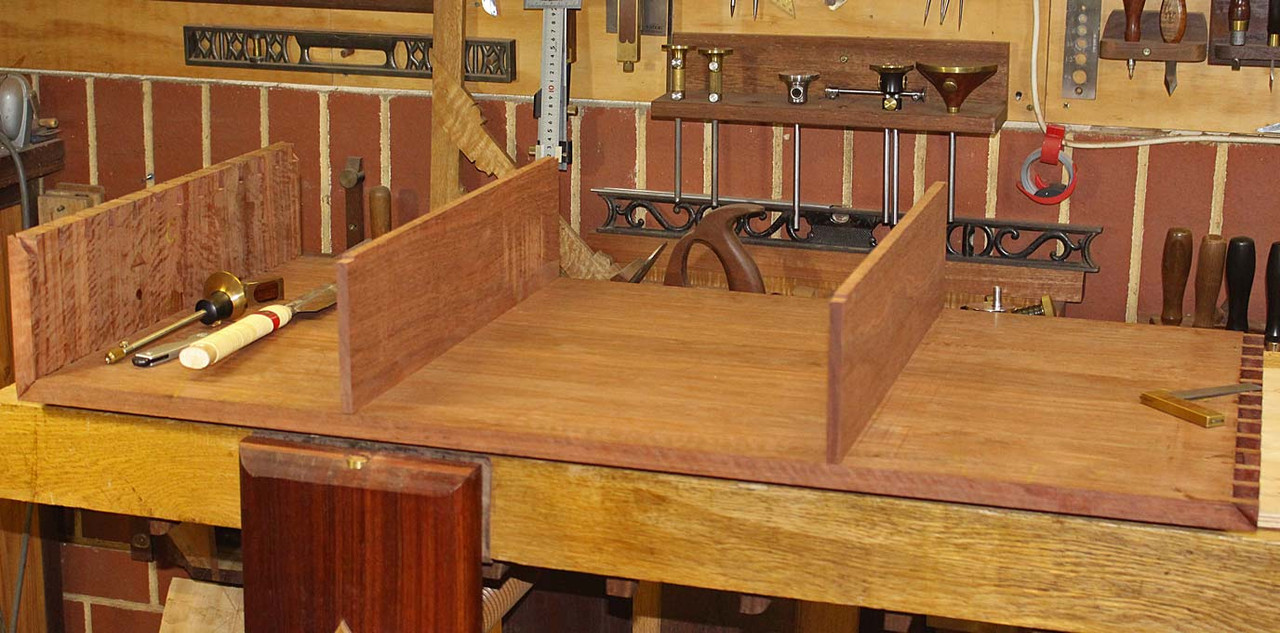
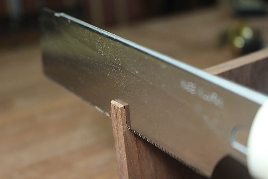
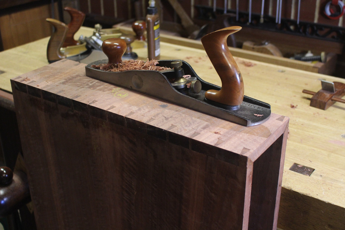
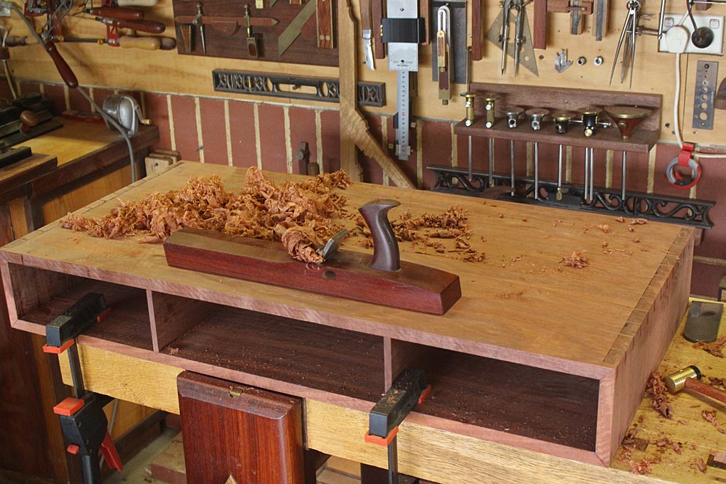
The joinery will be rounded corners shaped from through dovetails, mitred at each side. The challenge is to have accurately cut and fitted dovetails in hard Jarrah (no compression) as the outside will be removed in the rounding process.
The other challenge is the splayed and angled legs which, for added strength, will be fitted to a traditional rail design, that is, the legs and stretchers will be mortice-and-tenon joinery. The legs will splay from the corners.
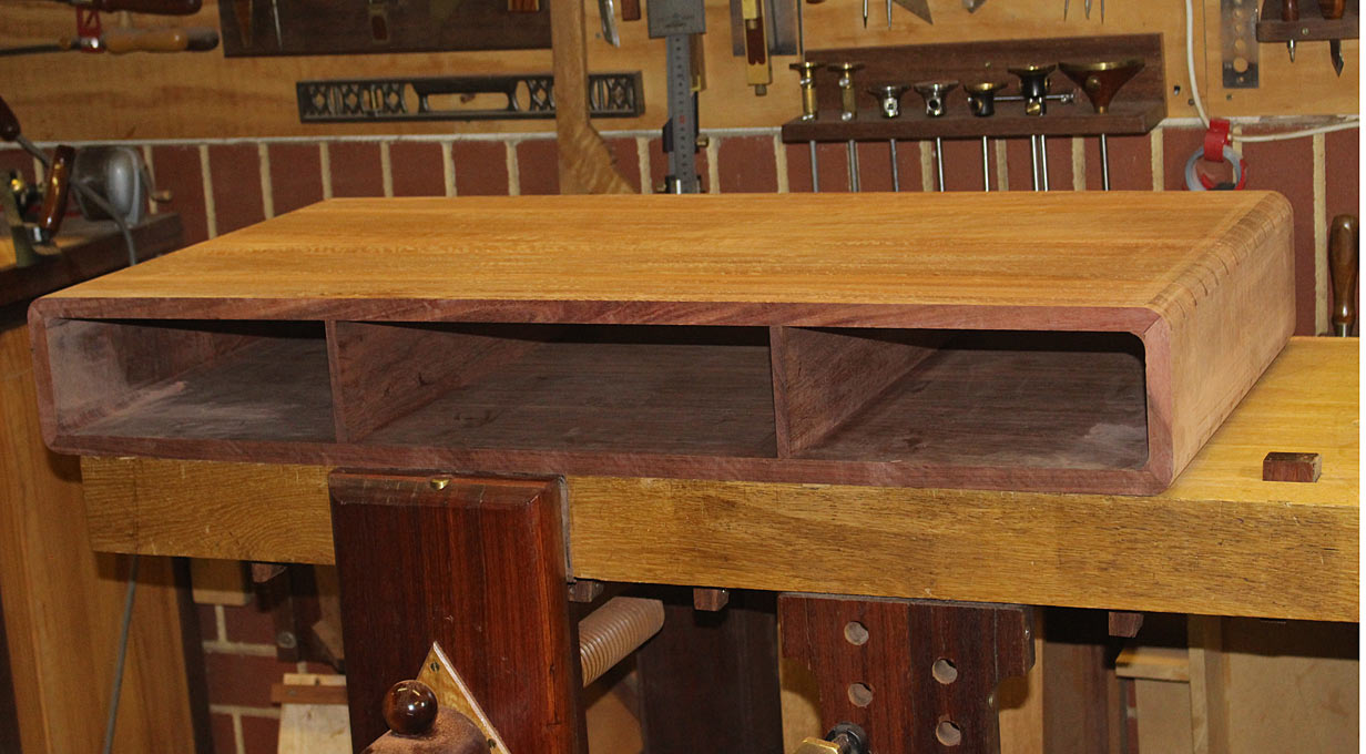
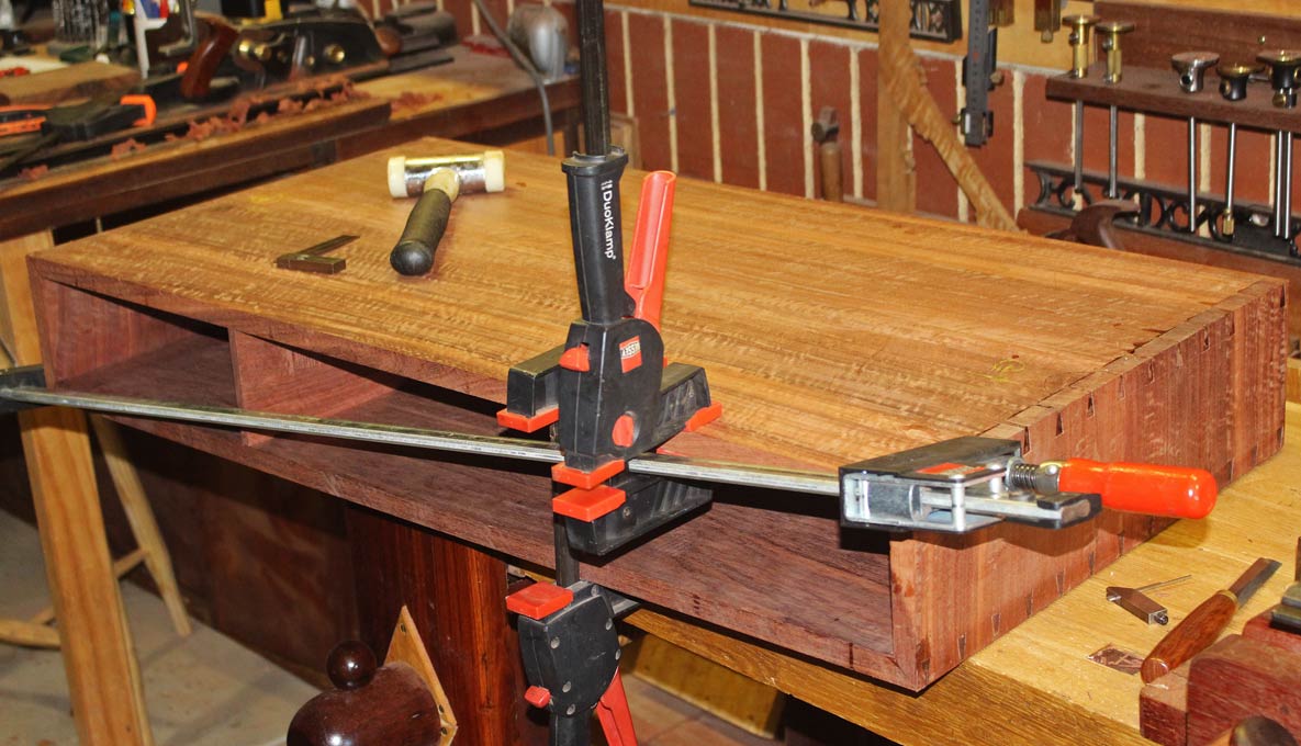
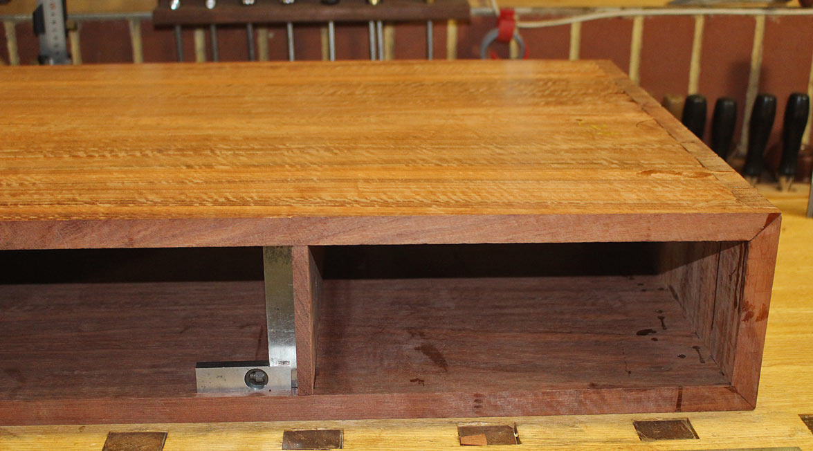
Lastly, the drawer will extend the full width, and be opened from either end. No handles.
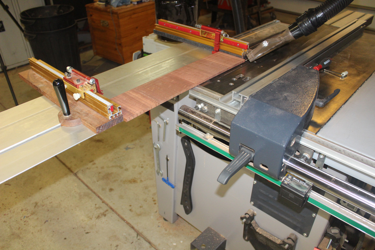
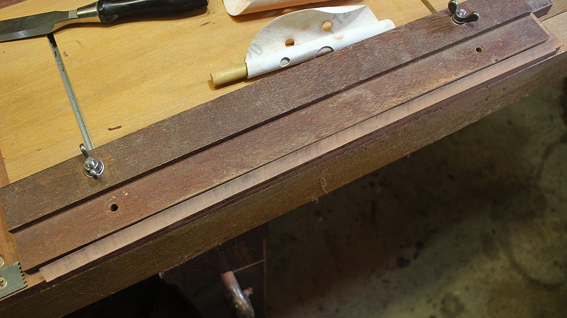
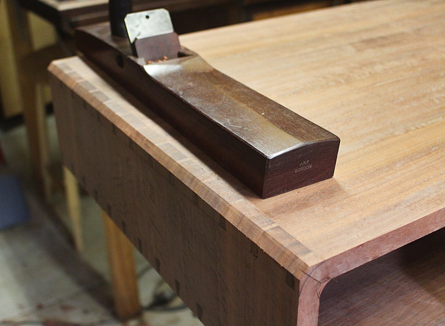
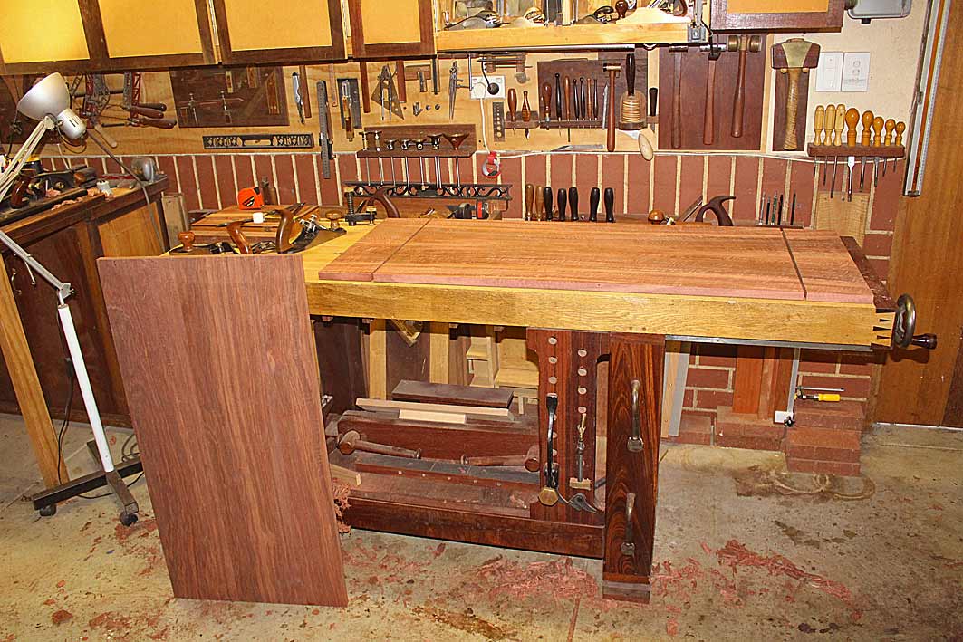
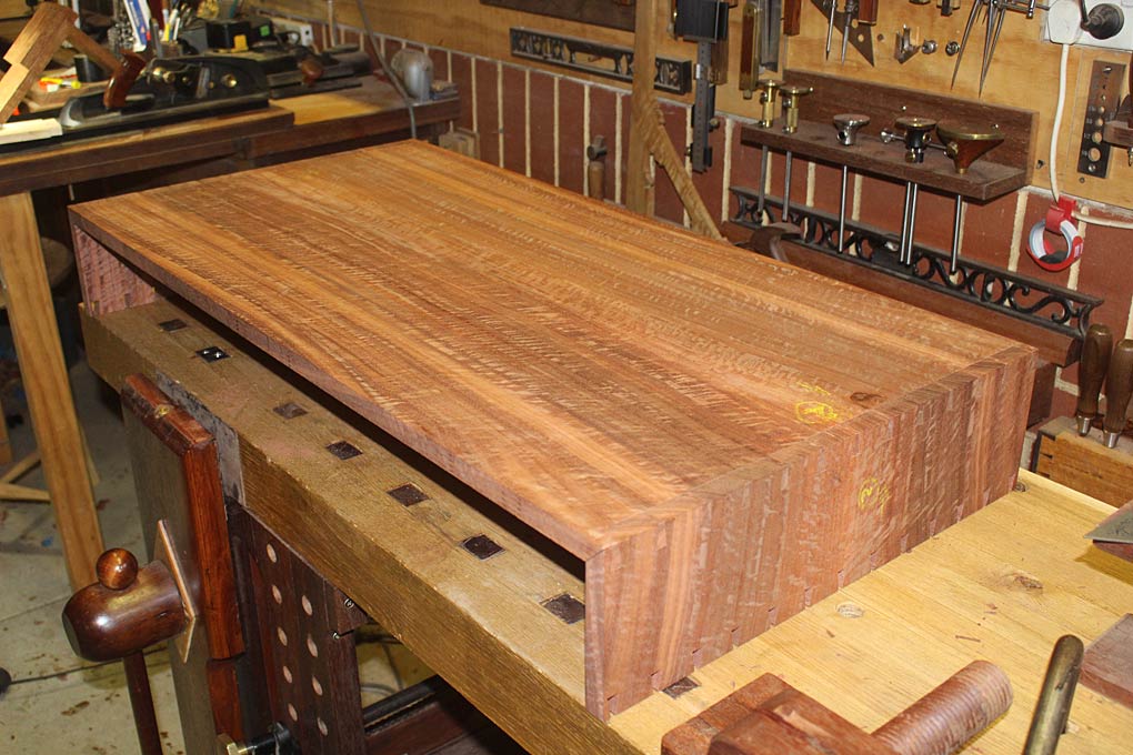
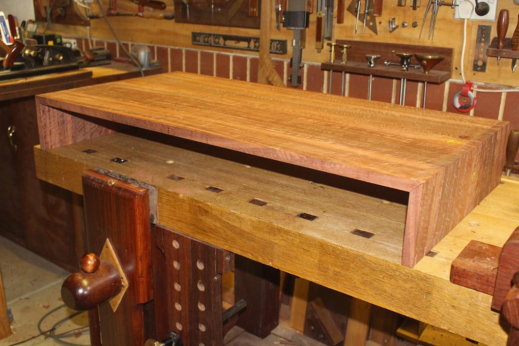
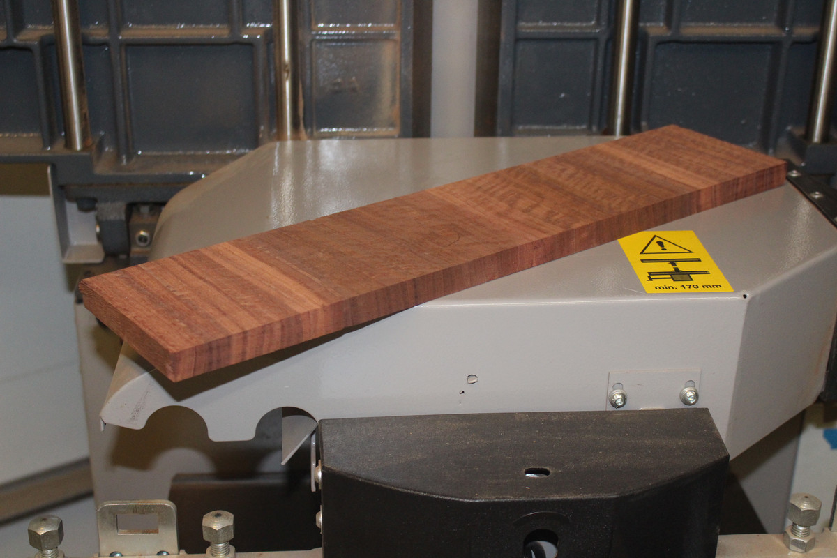
Beginning the prep by resawing some really nice Fiddleback Jarrah, which will be the top and sides. The length of the coffee table is 1000mm ...
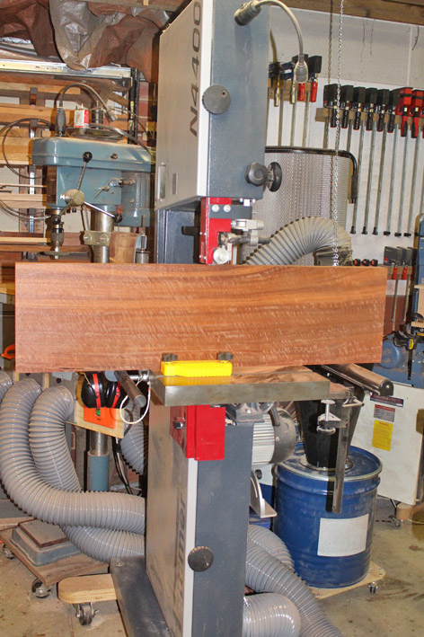
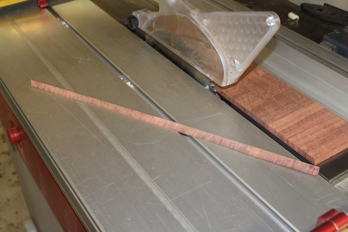
I was watching the boards come out of the blade, keeping an eye on the kerf for movement. This even kerf told me that the boards were going to be well-mannered and stable ...
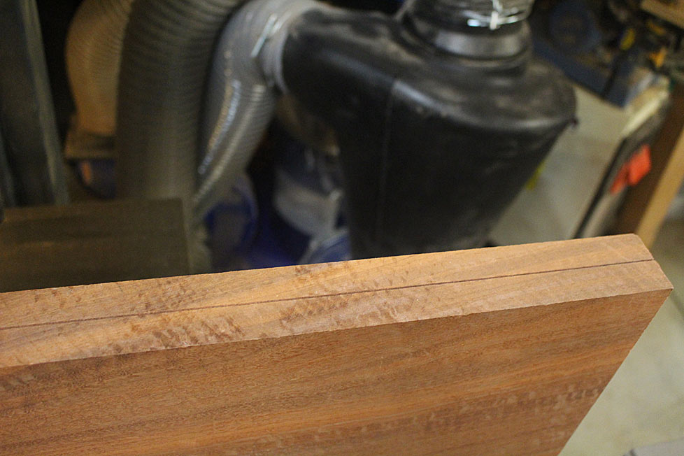
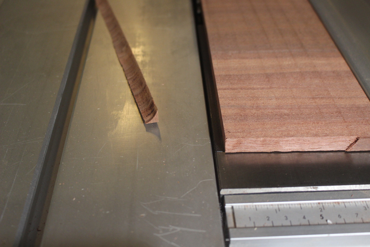
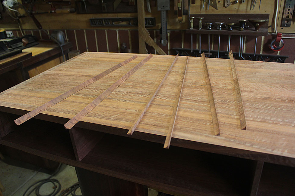
Here's an example of the figure. These boards will be bookmatched to create a width of 500mm ...
The lower side of the coffee table will be made of more "common" narrower Jarrah boards (still extremely nice!). I picked up a length 4m long, and then joined three together to get the width ...
The boards were stickered for a week ..
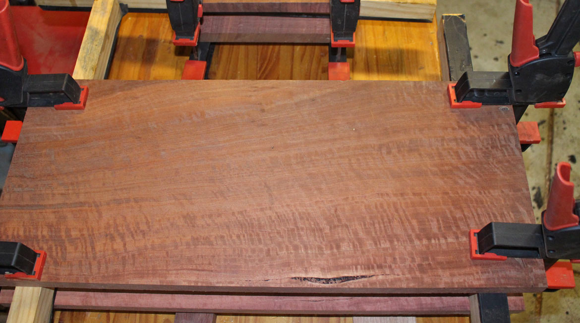
Some may have liked to have accentuated the centre figure this way when book-matching ...
Too busy for my liking.
I preferred this ...
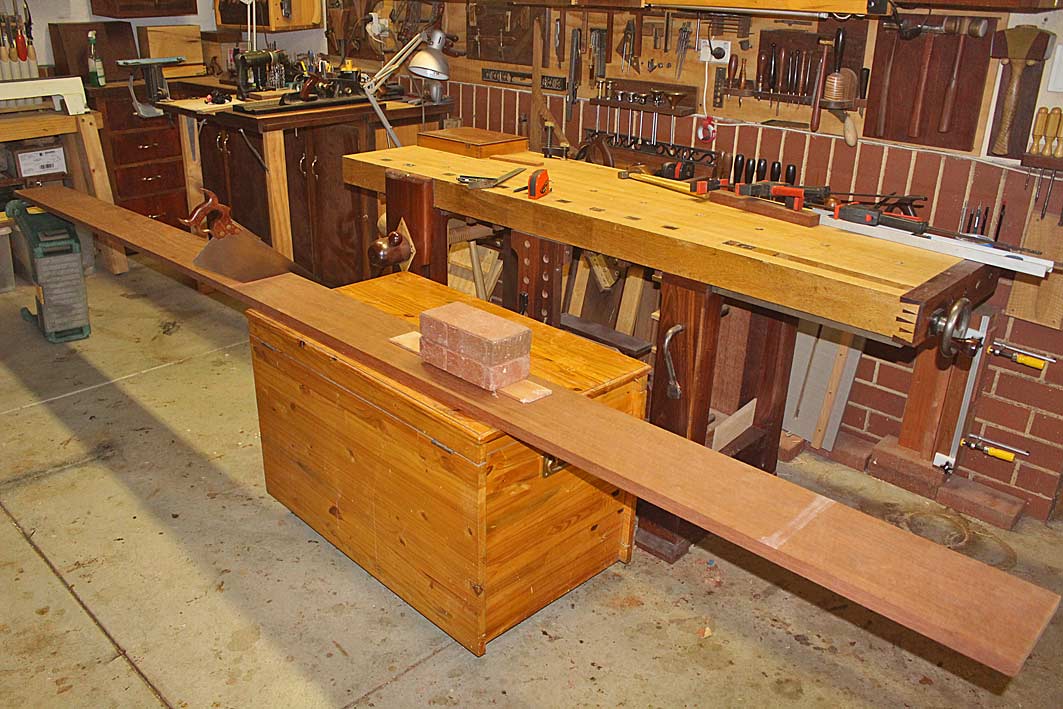
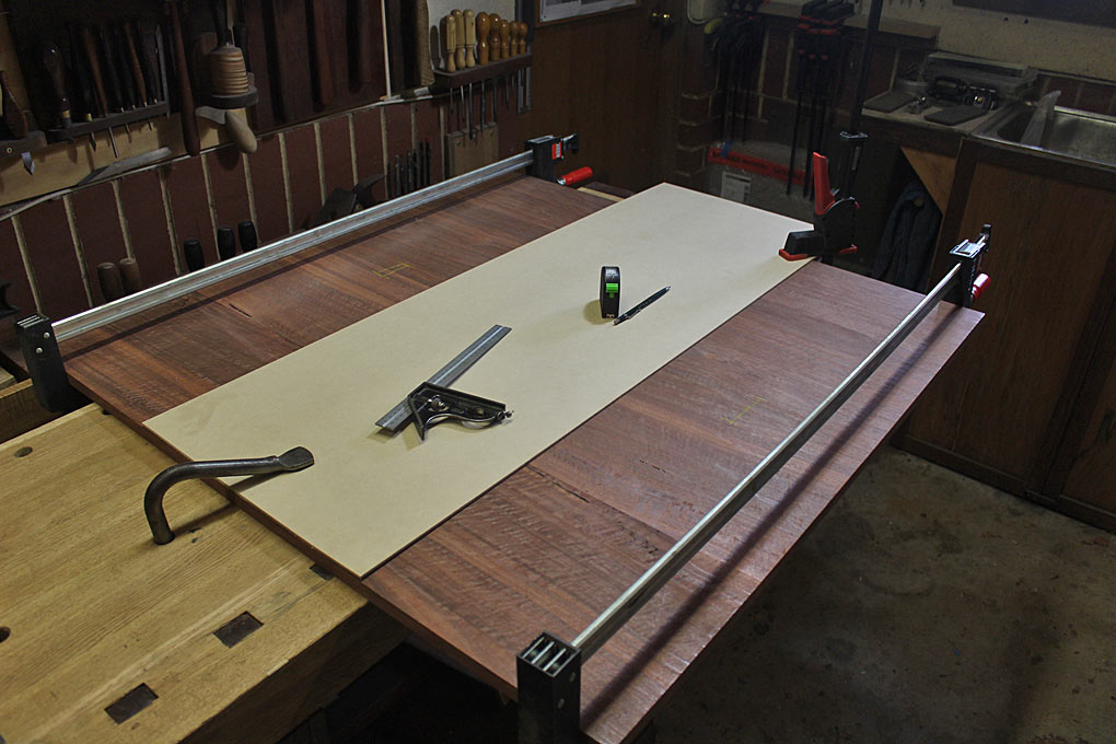
And this is where I left the boards at the end of last weekend ...
Regards from Perth
Derek
There shall be a few interesting challenges along the way since I am using solid wood and, I imagine, the "model" is built of veneered ply.
The joinery will be rounded corners shaped from through dovetails, mitred at each side. The challenge is to have accurately cut and fitted dovetails in hard Jarrah (no compression) as the outside will be removed in the rounding process.
The other challenge is the splayed and angled legs which, for added strength, will be fitted to a traditional rail design, that is, the legs and stretchers will be mortice-and-tenon joinery. The legs will splay from the corners.
Lastly, the drawer will extend the full width, and be opened from either end. No handles.
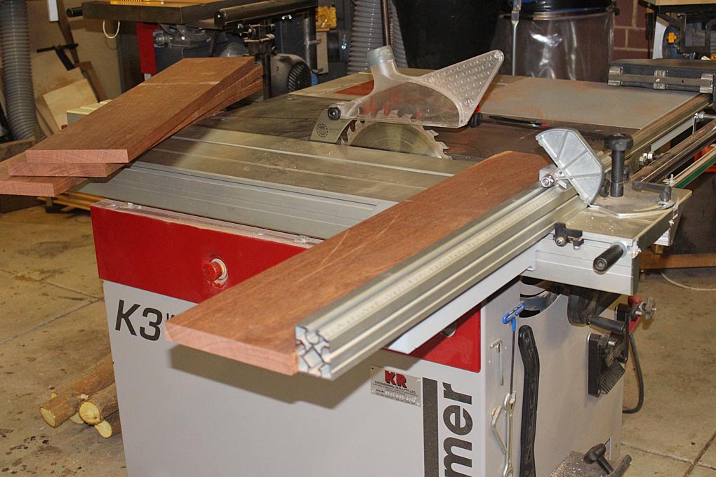
Beginning the prep by resawing some really nice Fiddleback Jarrah, which will be the top and sides. The length of the coffee table is 1000mm ...
I was watching the boards come out of the blade, keeping an eye on the kerf for movement. This even kerf told me that the boards were going to be well-mannered and stable ...
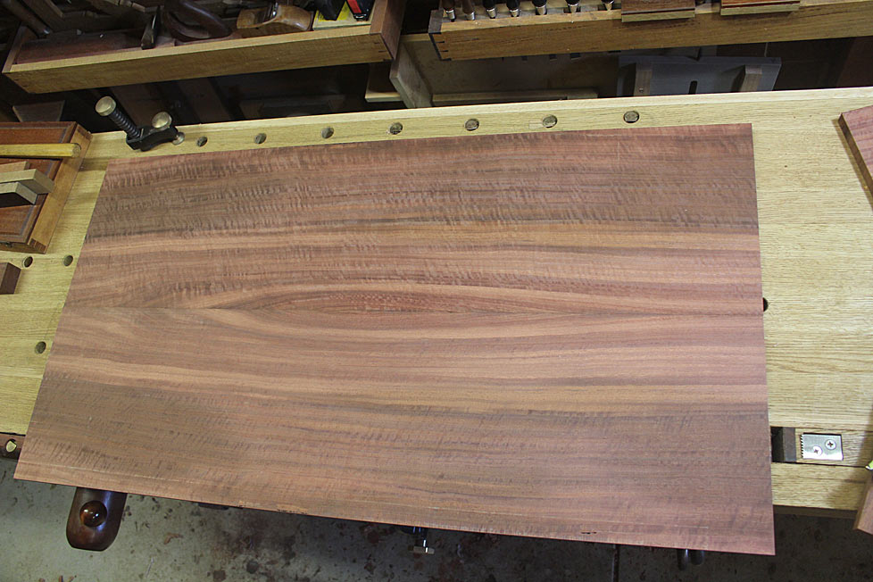
Here's an example of the figure. These boards will be bookmatched to create a width of 500mm ...
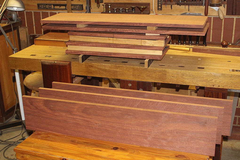
The lower side of the coffee table will be made of more "common" narrower Jarrah boards (still extremely nice!). I picked up a length 4m long, and then joined three together to get the width ...
The boards were stickered for a week ..
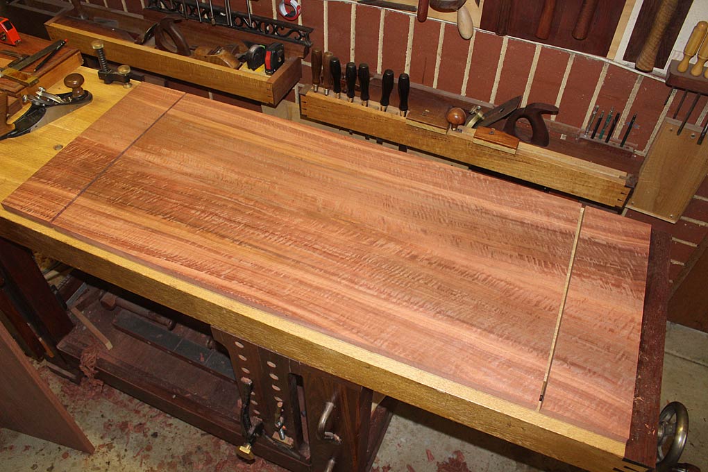
Some may have liked to have accentuated the centre figure this way when book-matching ...
Too busy for my liking.
I preferred this ...
And this is where I left the boards at the end of last weekend ...
Regards from Perth
Derek

")