LR32 Hole Guide Accuracy

gjfunk

Member
Joined
Jan 26, 2007
Messages
34
I recently purchased the LR32 system and guide rail and used it to make  an MFT style top for my outfeed table. It worked OK but I wasn't 100% satisfied with my top (couple of mistakes I made). I also had one made by a local shop with a CNC. When I received the CNC version I checked it against the one I made and after lining up the holes on one side the holes on the opposite side were off by 1/2mm or so.

The CNC shop had specified a tolerance of +/-.005" so I was mildly annoyed. Then I checked the holes with a couple of tape measures and the holes matched what I expected (11 holes 960mm). I went back to the 32mm guide rail and it was out by about .5mm in 1m.

I couldn't find any specs on the guide rail accuracy but I was a little surprised it is this poor. Has anyone else checked the spacing on their guide rail? Curious if I just have a bad rail or if I'm being too anal about this.
 
Using my construction Calc/Converter 1/2mm= .5mm= .019 which in the scheme of things IMO isnt bad at all. Im some cases wood moves more than that
 
I don't think you will find a tolerance spec.  As mentioned wood moves.  And some the amount of variation you saw is not going to cause an issue with shelves, etc. The moment weight is put on the shelf things will deform.  Also even if a hole is off 0.5mm  you still have to get the second row of holes to match, and then the holes on the other side of the cabinet to match them.  The .5mm hole to hole won't much matter.
 
Yes wood moves but the holes in the LR32 rail should be right on.

To dismiss the question about the accuracy of the rail because
'wood moves' is bull.

There was no wood involved in manufacturing the rail.
 
I agree with Bob D. 
Half mm error in one meter seems like a lot.
Not sure how Festool makes the holes.  Maybe they are punched and there is an indexing error in their fixture.
I don't have an LR32, so I can't help.  but would be good if those that do have LR32 would check their hole spacing over the full length and see if it is a perfect integer of 32mm.  Not sure that would prove anything though --- if 43 holes is 1375mm rather than 1376mm, is the rail out or your tape measure ?
 
Woodworking is not the same as aerospace engineering.  If anyone expects hyper precision with a hand operated power tool matched up to a portable user adjustable in some aspects jig then the odds are they will disappointed at some point in time.

Not a criticism, but rather an observation and opinion from me.

Peter
 
Bob D. said:
Yes wood moves but the holes in the LR32 rail should be right on.

To dismiss the question about the accuracy of the rail because
'wood moves' is bull.

There was no wood involved in manufacturing the rail.

You're not building the Space Shuttle even if you were there are acceptable tolerances +/- .

Not to mention what tool were the measurements made was that tool recently calibrated IAW ISO/IEC 17025 (equivalent to the relevant requirements of ISO 9000) and ANSI/NCSL Z540-1.

It should on a calibration schedule. If not then the measurements are for referance only and not exact.

 
I think when it comes to metrics, one should be very careful. It is indeed a rabbit hole. Wood moves, aluminum moves, everything moves. So the question quickly becomes, to what resolution do you wish to go and how do you plan on confirming your measurements.  The problem is the hand and the eye are able to resolve very fine differences in relative dementionality.

So I have a couple of questions.

Are you using the cnc made pattern as a reference. If so why? How are you checking it?
The reason I ask is that it can be difficult to figure where the issue is coming from, without a fixed datum.

What I would suggest is using you LR32 and make a series of holes the length of your track. I would then flip the rail, align the holes with sled and run the holes again and see what happens. With the router off and see how the holes line up. When I say flip, I mean rotate the rail. This should show any dimensional error in the track to become obvious. Also you could advance the rail and check. Just a thought.

After reading your post this is what I did. My holes lined up with all my holed rail. As a mechanical engineer I find these issue fascinating. I would never thought to have checked the hole spacing on the rail as I have had no cause. I would suggest that when you do you r test you do it relativily quickly, this way variations in Temp and humidity will be minimized. 
 
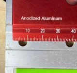
Here's a Woodpeckers aluminum rule on top of the Festool aluminum rail. Both have been at the same temperature since the last week in November. [smile]  At the 960 mm measured distance (970 mm shown) there is a discrepancy of about 1/3 mm.

What we don't know though is which item is to blame? Is the rule off or is it the rail?

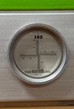
Just to make life more interesting I noticed the hash mark at 10 mm is narrower than the hash mark at 970 mm, that can readily be seen. So I measured the width of the 2 hash marks with a pocket comparator and indeed, the 10 mm mark is .010" wide while the 970 mm mark is .015" wide.  How does that add to the equation...rabbit hole indeed.

[attachimg=1]

[attachimg=2]

This is a closeup of the pocket comparator scale

[attachimg=3]

This photo provides some semblance of real world scale.

[attachimg=4]
 

Attachments

  • 8328.jpg
    8328.jpg
    395.6 KB · Views: 1,570
  • 8329.jpg
    8329.jpg
    366.4 KB · Views: 1,492
  • 8330.jpg
    8330.jpg
    170.9 KB · Views: 1,527
  • 8331.jpg
    8331.jpg
    355.8 KB · Views: 1,507
... And at the end of the day the only thing that matters is if the shelf rocks on the pins.  And if it does, wait 48 hours and test again.

Peter
 
Interesting discussion.  In my somewhat limited experience I'm sure I've introduced most of the error when using the LR32 to do what it is intended for:  making shelf pin holes and drilling for Euro Hinges.  In that regard the LR32 excels, even for me.  (I've tried using several other jigs and methods.  My shelf's rocked EVERY time!) 

As for MFT tops here's my take: 

If my goal is to simply replace the top of my Festool MFT/3 I will spend the money and simply buy the replacement part.  There is simply no way I can make an exact copy as cheaply as I can buy one.  If my goal is to produce a surface to be used for work-holding I've been know to take out my trusty rusty 3/4" spade bit and make some holes in a scrap of OSB.  If I want a precision top in a size other than the standard MFT/3 I use my PARF Guide.

Peter Halle said:
... And at the end of the day the only thing that matters is if the shelf rocks on the pins.  And if it does, wait 48 hours and test again.
And if the shelf DOESN'T rock,  DO NOT test again! [big grin]
 
All this talk got me to go out to the shop and check some of my items.

First off, I compared my Stanley Fat Max tapes to my Lee Valley metal rule. They pretty much were spot on with each other over the 1 meter length of the metal rule.  I checked two serarate Fat Max tapes, one was a 5 meter and the other, an 8 meter. I also compared my Tajima tape to the Lee Valley rule and it matched as well.

I have a 24”/610mm blade for my Starrett try square, so I compared the Lee Valley rule to it and again, had a match.

When I say my rules matched, I’m going with what these old eyes can distinguish. I did grab a small magnifier at times to get a better view, but only when the items didn’t match up. 

Those items were my Woodpecker rules. Comparing those to my other items did not come up as well. I showed over .5mm longer on my longest Woodpecker rule, and my 900 also read high under comparison.  The shop has been sitting at 59° for the last week if that means much.

I also checked some Fastcap tape measures against my Lee Valley “Standard”.  Both of them a 16’ Standard/Metric, and a True 32 read low. The matched each other, but not the Lee Valley. I’ve never believed them to be “trustworthy” accurate, but they were both closer to my standard than  the Woodpecker rules.

All the measuring devices made of steel, (excepting the Fastcap tapes), matched each other while the aluminum measuring rules both seemed to be of a reduced length, maybe because of the cooler temp? 

However, when I measured my 2424 LR-32 rail, (also of aluminum), my holes were pretty much spot on with my Fat Max tape over the length of the entire rail. I did not, however check the 1080 LR-32 rail that I also have.

Take what you will from this. I, at least now, feel confident that my Fat Max tapes, the Tajima tape and my set of Lee Valley rules are precise enough to match up well with my Starrett, (which I’ve always believed to be accurate.) If I feel I need the most precise measurements I will not be grabbing my Woodpecker rules. I still believe they’re accurate enough for nearly everything I do, and if the temperature, and the rules were both warmer, they might match spot on as well. My Fastcap tapes will be used, but for items where I’m not worried about precision. I just need to be sure to not mix my Fastcap tapes or my Woodpecker rules with the other rules on the same project.

 
Cheese said:
Here's a Woodpeckers aluminum rule on top of the Festool aluminum rail. Both have been at the same temperature since the last week in November. [smile]  At the 960 mm measured distance (970 mm shown) there is a discrepancy of about 1/3 mm.
Thanks very much for measuring. Your guide looks right on to my eye, certainly much better than mine. In my case 3 different tape measures and the CNC routed top all agreed but the LR32 was off.

I appreciate everyone's comments. At the end of the day it's not a big deal but I had a little higher expectation from Festool.

I made a few more measurements with Mitutoyo calipers and the distance between the 6mm holes is not terribly consistent. It should be 26mm but in my case it varied down to as low as 25.85. I suspect over time the holes will enlarge as they wear with use. I can notice which holes were used (every 3rd one).

As long as I reference from the same edge when drilling holes it should be fine.

Thanks again for all the comments and measurements!
 
tallgrass said:
So I have a couple of questions.

Are you using the cnc made pattern as a reference. If so why? How are you checking it?
I originally put the cnc pattern on top just to make sure the top matched my drawing. After that I measured with several tape measures which all agreed.

What I would suggest is using you LR32 and make a series of holes the length of your track. I would then flip the rail, align the holes with sled and run the holes again and see what happens. With the router off and see how the holes line up. When I say flip, I mean rotate the rail. This should show any dimensional error in the track to become obvious. Also you could advance the rail and check. Just a thought.
If the holes were equally spaced at 33mm I think your procedure, as I interpret it, would look OK as long as the holes were consistently spaced.

This is only an issue if one needs to compare against a more accurate reference. It shouldn't be an issue drilling holes for a 32mm cabinet system as all the hardware is adjustable by much more than .5mm.

As far as the MFT top, I don't think it matters to me if the holes are 32 or 33mm apart. I don't particularly even need them to be square although I'm sure it might be handy sometimes.

I do like the way the bench dogs fit in the cnc top. I gave them a couple samples and they came out perfect. The ones I drilled with the 20mm festool bit are a little sloppier. Again, not a bit deal for my purposes but it's nice to have a tight fit. I'll have to be careful if I buy any more bench dogs as anything larger than what I have won't fit.
 
If the holes were equally spaced at 33mm I think your procedure, as I interpret it, would look OK as long as the holes were consistently spaced....................................................................

"Consistency is accuracy." If the holes line up than they are equal and as you move the rail and the hole stay in alignment you have repeatability. The corner stone of manufacturing. Just like the MFT hole pattern. If they align , no matter what the orientation is , than you have the geometric construct that you need. For if the holes line up, what can the measurement be, if there is no meaningful deviation.? This like checking a square. If you scribe a line then flip the square and it aligns, you have a good square. If it does not, well then. Does it matter what you are able to measure? If the scribe line matches but you "protractor says 89.1, which is correct? This is while I prefer self check geometric construction.

The reason I suggest this kind of self validating check is the uncertainty of your references. We all take for granted what we have is what we think it is. However few check, or have the means to. I am fortunate, I have temperature control and granite references and on and on , which are calibrated annually.  There is always a tolerance.

So in the case of your holed rail, if the holes line up as you shift the rail or flip it, than that is "perfect" for all intents and purposes.  you will get a repeatable hole pattern. That is the true goal.

 
jobsworth said:
Bob D. said:
Yes wood moves but the holes in the LR32 rail should be right on.

To dismiss the question about the accuracy of the rail because
'wood moves' is bull.

There was no wood involved in manufacturing the rail.

You're not building the Space Shuttle even if you were there are acceptable tolerances +/- .

Not to mention what tool were the measurements made was that tool recently calibrated IAW ISO/IEC 17025 (equivalent to the relevant requirements of ISO 9000) and ANSI/NCSL Z540-1.

It should on a calibration schedule. If not then the measurements are for referance only and not exact.

Exactly so anything anyone here has done to make comparisons between various rules, rails, whatever is "Information Only" unless the measurements were taken with calibrated equipment under controlled conditions. The guide rails have no stated accuracy for hole spacing that I am aware of, there is no calibration sticker or accuracy statement stamped on my LR32 rail anyway.
 
gjfunk said:
I made a few more measurements with Mitutoyo calipers and the distance between the 6mm holes is not terribly consistent.

Interesting.  I wonder if Festool uses something like a 2-hole or 4 hole punch die, and indexes the rail through.  (rather like a box joint jig)
 
Here's what I do to negate any and all error with the LR32 guide and sled and the work piece itself.

I always register from the bottom and from the front of the work piece and I never flip the guide around. 

This requires that you provide another piece the same thickness as the work piece sitting on the table beside the work piece for one of the hole columns.  The guide will rest on this other piece.

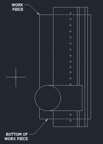
I've attached illustrations.  Let's assume the front of the work piece is to left. 

Here's the set up for the first column of holes.  No sweat it's just like normal Festool endorsed LR32 practice.

[attachimg=1]

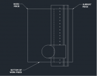
Here's the set up for the second column of holes toward the back of the work piece.  Notice the support piece.  All I do is slide the guide over far enough.

[attachimg=2]

I've rigged this up a number of ways including setting the LR32 guide up on my MFT.  Each row of holes will be pretty much exactly the same distance from the bottom.  So the shelf or the drawer guides will be level even if the guide is drilled inaccurately or if the router is a little off in the cradle.  It works even if the two sides are cut a little off.


Attachments

  • First column.png
    First column.png
    14.2 KB · Views: 1,405
  • SECOND COLUMN.png
    SECOND COLUMN.png
    17.2 KB · Views: 1,310
Back
Top