MFT cart concept - overkill?

ChiknNutz

Member
Joined
Mar 9, 2017
Messages
85
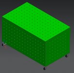
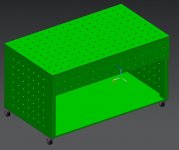
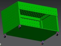
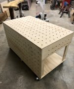
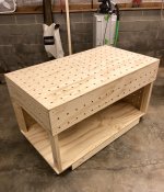
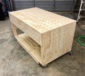
Planning on building a custom MFT mobile cart.  I currently have no need for it to be portable, but do want it mobile.  Here is my concept.  I wanted to build something with at least one 90 degree face with dog holes, then went a bit overboard.  I figure you can't really have too many holding options, can you?  Still...is this more hassle than it might be worth in regards to drilling all the holes?  Overall size is 62.5 L x 36 W x 36 H.
 

Attachments

  • MFT_01.jpg
    MFT_01.jpg
    41.5 KB · Views: 319
  • MFT_02.jpg
    MFT_02.jpg
    43.5 KB · Views: 295
  • MFT_03.jpg
    MFT_03.jpg
    51.8 KB · Views: 319
Probably overkill but maybe useful at some point.

If this is your hobby don’t let practicality take the fun/challenge out of it.

Enjoy!
 
Hi
I might suggest looking at the Stanton Bench for ideas on the vertical holes. Dave Stanton’s idea is for a portable bench but he seems to add vertical holes without the overkill you mentioned  I have even seen designs where a vertical section of holes is moveable (it slides into the needed positions)or even removable Similar to a Deadman. One thought I had was all of those vertical holes on your initial sketch may not be necessary and having  shelves or drawers to toss tools in to clear the horizontal surface midway through a project might be helpful without having to walk around to the open side to clear off your bench top.
I wish you well with your project
Best
 
Started working on the table, go the top finished is all so far.  Was a little slow going at first getting used to the Parf system.  Was also able to use my recently acquired TS75 which I had so far only used to trim the bottoms of two interior doors.  Really impressed with how nice the cut is, better than any cutting tool I have used so far.

Not sure how to correct the pix being rotated.  I rotated them and then re-uploaded but show up the same.
 

Attachments

  • MFT top 03.jpg
    MFT top 03.jpg
    678.8 KB · Views: 327
  • MFT top 02.jpg
    MFT top 02.jpg
    563.5 KB · Views: 347
  • MFT top 01.jpg
    MFT top 01.jpg
    611.6 KB · Views: 374
Completed it today and backed off on the size of one of the panels but overall essentially the same. Have yet to use it though.
 

Attachments

  • 9CE5F95C-8502-4A53-894F-6E7605D9EC11.jpeg
    9CE5F95C-8502-4A53-894F-6E7605D9EC11.jpeg
    2.4 MB · Views: 381
  • C7D40181-ED5B-4B1D-87B4-6E0662315DD5.jpeg
    C7D40181-ED5B-4B1D-87B4-6E0662315DD5.jpeg
    2.4 MB · Views: 444
  • 71942E91-41FA-4D49-8695-192884ACE9F9.jpeg
    71942E91-41FA-4D49-8695-192884ACE9F9.jpeg
    2.1 MB · Views: 390
Looks great! Any tips on getting those end side panel holes in line with the top mft holes? Thanks
 
AndrewG said:
Looks great! Any tips on getting those end side panel holes in line with the top mft holes? Thanks

I designed it all in CAD with the hope that all would line up when assembled, but I cannot yet verify that the end panels do in fact line up exactly.  I have only got it assembled and still have to verify the accuracy of my production and assembly methods.
 
Back
Top