Wooden Skye said:
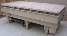
I was wondering if anybody has ever routed the MFT hole pattern in a torsion box top. I am trying to design an outfeed/assembly table and would like to have the hole pattern. I realize that with the grid, some clamping options may be restricted. If anyone has done something to this effect, could you share a few pictures, plus any pros and cons after using.
Thanks
Bryan
I never thought about doing that. Building a torsion box assembly table is on my to-do list as I complete my workshop, and your post has spawned some deep thought on the idea of using MFT tops. [smile]
In my mind's eye, I would probably use two tops for a full size assembly table, and plan the positioning of the underlying grid to "miss" the 20mm holes in the top. I currently use my MFT/3 standalone for assembly, and cover the top with construction paper to keep glue and finishing products off the surface. I punch a hole through the paper when clamping is needed.
That being said, the MFT/3 table "wobble" is too evident when working with heavy pieces, so the torsion box has been one of my plans.
Thanks for posting that. Great idea! [big grin]
Cheers,
Frank