Modified Seneca/Incra Parallel Guides

Bugsysiegals

Member
Joined
Mar 19, 2016
Messages
908
Happy Holidays Everybody,

I've finally some Holiday vacation time and thought I'd take the time to share how I've modified my Incra parallel guides.

To begin with, I did this mod because it's always bothered me to get both parallel guide end stops set to the exact same measure.  Besides this, as I rip multiple panels for a project, I always wonder if any little errors will compound into bigger errors by the end of a project.  I have the Incra Precision Joinery fence on my SawStop and wished these PG's had the same capability ... rather than waiting for somebody to create them I decided I'd do it myself ...

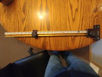
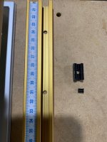
To begin with, I ordered Low-Strength Steel Threaded Rod, M6 x 1 mm Thread Size, 1 M Long which fits the Incra t-track perfectly.

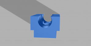
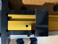
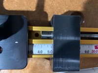
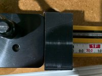
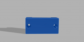
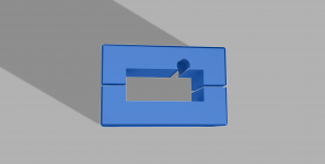
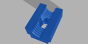
I then used Fusion 360 to design t-track brackets the threaded rod could screw into in order to hold it in place both vertically and horizontally.  The brackets are "U" shaped and hold the bottom half of the lead screw.  And in order to stop them from moving horizontally, I created a vertical hole which allows a pin to be inserted which locks it into position using the hole at the bottom of the t-track.

View attachment 1 View attachment 2 View attachment 3 View attachment 4 View attachment 8

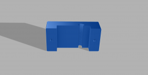
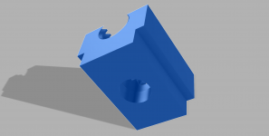
Finally, I designed the end stops which are two "U" shaped brackets.  The top piece is designed to hold a small piece of the M6 threaded rod and the bottom has a recessed hole for springs and screw to allow these to be spring loaded end stops.

View attachment 5 View attachment 6 View attachment 7

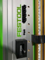
I've replaced the stock Incra measuring tape with Starrett measuring tape.  It was difficult to insert and is not movable horizontally now that it's inserted.  Since I cannot move the measuring tape, in order to calibrate, rather than pushing the t-track into the Seneca adapter until it bottoms out, I place my end stop at 52mm (based on where my measuring tape is positioned), slide the t-track into the Seneca adapter, and tighten it down.  This leaves a ~1mm gap between the end of the t-track and Seneca adapter and I make micro adjustments by turning the lead screw on the end stop which affects how deep the t-track seats into the Seneca adapter which allows calibration of cutting width.

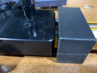
Here's the lead screw almost flush with the end stop...

View attachment 12 View attachment 11 View attachment 13

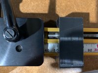
Here's the lead screw protruding past the end stop...

View attachment 14 View attachment 15 View attachment 16

I no longer have to wonder if both end stops are set the same or spend time comparing the two wondering if my eye is in the right position to reduce parallax.  I simply lift up on the top section of the end stop, slide it to the measure, and release the end stop which takes a few seconds compared to 10's of seconds if not a minute when I was comparing the two back and forth to ensure they're the same.  In addition to how quick these are, and not worrying about the accuracy, the fact the screws always mate the same way every time allows me to come back and rip a panel after the fact to the exact same width of a previous panel just like my Incra Precision Joinery fence on the TS which is a game changer for me so I figured I'd share...

View attachment 9 View attachment 10
 

Attachments

  • Incra T-Track 6mm Rod Holder 1.png
    Incra T-Track 6mm Rod Holder 1.png
    94.1 KB · Views: 255
  • IMG_2736.jpg
    IMG_2736.jpg
    647.1 KB · Views: 248
  • IMG_2735.jpg
    IMG_2735.jpg
    668.2 KB · Views: 240
  • IMG_2734.jpg
    IMG_2734.jpg
    730.2 KB · Views: 272
  • IMG_2733.jpg
    IMG_2733.jpg
    685.1 KB · Views: 275
  • IMG_2732.jpg
    IMG_2732.jpg
    694.4 KB · Views: 323
  • IMG_2730.jpg
    IMG_2730.jpg
    563.8 KB · Views: 263
  • IMG_2044.jpg
    IMG_2044.jpg
    180.4 KB · Views: 296
  • IMG_2043.jpg
    IMG_2043.jpg
    310.2 KB · Views: 345
  • IMG_2045.jpg
    IMG_2045.jpg
    307.5 KB · Views: 299
  • Incra T-Track 6mm Rod End Stop 3.png
    Incra T-Track 6mm Rod End Stop 3.png
    44.7 KB · Views: 197
  • Incra T-Track 6mm Rod End Stop 2.png
    Incra T-Track 6mm Rod End Stop 2.png
    74.6 KB · Views: 207
  • Incra T-Track 6mm Rod End Stop 1.png
    Incra T-Track 6mm Rod End Stop 1.png
    67.8 KB · Views: 201
  • Incra T-Track 6mm Rod Holder Pegs 1.png
    Incra T-Track 6mm Rod Holder Pegs 1.png
    54.1 KB · Views: 199
  • Incra T-Track 6mm Rod Holder 3.png
    Incra T-Track 6mm Rod Holder 3.png
    96.6 KB · Views: 202
  • Incra T-Track 6mm Rod Holder 2.png
    Incra T-Track 6mm Rod Holder 2.png
    150.8 KB · Views: 206
this is amazing...
I have had the Seneca PG for a few years...
I am techy, but these things have tricked me so many times, for the reason u describe... despite the two showing the same measurements, they were NOT parallel, and I was stumped as to why, so I gave up and use other systems, but would like to get back with them.
So what is the shortcoming with this system??
I am a bit confused about your solution...can you show a pix of the entire system in use?  I assume u have to lift the bracket and clamp it down over the lead screw just like you do on the Incra system?
Did u 3d print all those parts?
The Seneca PG system seems like it would have been a great system, but it has failed me, any help would be appreciated.
 
I have to rip some drawer box bottoms in the coming week and will make a video demonstrating the PG’s.

What PG’s did you end up switching to?
 
great share, thx Buggsy
I too have the Seneca PG, and consistently had the same problem
they are set up right, but yet, cut is not parallel!
I too am technical, and I was stumped and simply used other methods...
I asked Seneca, they were baffled, and could not explain it...
anyway, would love to see in more detail of what you have created here..
as I too am a bit confused of your fix...
looking forward to seeing the solution!
 
Wow, great job. I struggled with the Seneca guides also and felt the sliding scales were a weak link. I routed the scale slot out to 1/2" and applied a adhesive backed tape rule. I made sure the tape was a little short so the T track was a little to far in to the bracket. Then I installed a t nut in the back side that I could use to calibrate the guide.

I still struggle with the bolt holding the stop as if it is not very tight the stop will move. I very much like the way your stop bites on the threaded rod. That will not be creeping ;)


Attachments

  • scale side of guide.jpg
    scale side of guide.jpg
    1.1 MB · Views: 346
  • back side of guide.jpg
    back side of guide.jpg
    936.2 KB · Views: 313
seems odd we all have this problem, and we cant figure it out the cause...
my scales are always locked in, they are tight, so they are not moving...
my connection on the rail is tight, that is not moving...
set up is done meticulously....
and yet, I would never get parallel cuts!
has anyone presented this to the maker?
 
I bought the TSO Guide Rail Square and then decided to buy their PG's to complete the system.  That said, I've not had time to cut drawer boxes with either system so I'll describe what's going on here the best I can.

Calibration of these PG's is done by how deep the t-track seats into the guide rail adapter.  How far it seats is adjusted by setting the spring loaded clamp (piece that buts up to the edge of the panel) to a specific measure (depends on your scale position), adjusting the lead screw on the spring loaded clamp, and then inserting the t-track into the guide rail adapter.  By adjusting the screw so more of it is protruding, it reduces how far it seats and vice-versa.

About the downsides ...

I forget which measure I need to set the spring loaded clamp to when installing the t-track but can quickly figure it out after looking at the gap since I've about 1mm gap. Nonetheless, it's not as easy as it could be and because the scales and threaded rod can be located differently on each track, even if just a small amount, you need to keep the spring loaded clamp which has a different amount of lead screw protrusion with it's corresponding t-track.  That said, the set stop on the underneath of the t-track, shown above, is awesome and I'd switch to that if I was still using these.  In this way, you calibrate the t-tracks, lock in the set stop and then just insert the t-track and lock it down without any thinking involved.

Lastly, the only other downside I noticed is the clamp is spring loaded so it can begin to rotate clockwise, making a longer cut than desired, if you pull to hard on the guide rail, but worked fine for me since I knew not to Hulk it.

If you've any other questions regarding part numbers, 3D model files, or if this wasn't clear let me know and I'm happy to share and elaborate. 
 
Thx for the added input...
I will have to re read this a few times, then re look the Seneca PG system, as I have laid it to rest... which is a shame, as I bought so many of the Incra rails to make for a well rounded system.  But it was all so unreliable, I abandoned it, and till this thread, forgot about it.  Sure glad Buggsy found a solution, which maybe his video will make the problem and solution crystal clear.

A few General comments here regarding rail placement.

1)  I also have the TSO square for the rail... TSO makes very precision machined products for sure.  But in this case, "square" relies on the rail itself, not just the TSO component...and this also turned out to be unreliable.  When I insert the TSO rail square and check with largest 26" WP square, the Blue Square is NOT square to the WP square.  This is NOT a defect of the TSO product, instead, its a tiny difference at the connection between the TSO product and the rail, a few thou at most.  It took some blue tape to make up that difference to get it square.  When cutting an 8ft sheet using this method, the smallest out of square will magnify out of squareness at the other end.  IMO, trying to make a large run, such as 8ft. square at one end is not an ideal system.  for 2ft, prob. yes, as the error at the end would be 75% reduced.  The Festool rails are not robust extrusions.  If the rails were designed knowing of all these aftermarket products being inserted in them, I would have suspected they would have reinforced the back area of the rails.  So I am very careful when using end squares.  Again, this is not a knock of the TSO product, its just a warning that any end rail square represents half the equation to square, its not always plug n play, always confirm.

2)  After the frustration of the Seneca PG, I developed a different placement system for my rails.  As users well know, there is two types of cuts on a rail system.  First the usable work piece is under the rail, typically larger pieces.  (blade kerf is not relevant, as kerf is taken from waste piece)  Second, the usable piece is in front of the rail, such as cutting multiple strips.  (kerf is removed from the usable piece)

The simple system I developed works well, is simple, fast and with a little bit of practice produces parallelism as good as any system I have tried.  I use two WP rules with WP-2 stops.
main2_rule_stop-2_2_9.jpg


If I want 20" pieces, I set the stop at 20"+ kerf, ~1/8".  Or add a 1/8" kerf block to front of rule if you dont want to remember to add kerf.  I place the two rules about hip distance apart, set rail closer than 20".  I then push the rail forward using the 2 rules, holding the rules flat to the work piece... when the stops hit the end of the work piece, the rail is parallel and set to the proper cut distance.  No longer do I need to do the up n back rail dance as when marking one end.  It's reliable, fast, and u can teach others to do it quickly.  I learned, once the stops are close to touching the material, go slow, try to push them so the both touch at about the same time.  maybe 5 seconds is all it takes.

There is some downsides... you need at least two rule length pairs and 2 stops.  So its not cheap by any means as you can see the prices of the rules and stops.  OTOH, the rules are very accurate and have many other uses.  However, there is other rules on the market with stops, or you can make your own using some Starett tapes and their are many stops on the market... even incra products would work.  The WP rules are pretty wide so they have decent surface contact area to the rubber cutting strip on the rail.  The wider this is, the better, hence a homebrew solution would be even better.

The other downside is, Cutting 4ft pieces is cumbersome as the rail is far away, and would require the WP 49.5" rule.  With tax and ship is prob. $90+ each.  But they are very accurate vs. marking with a tape measure, so u can weigh the pros n cons of the longer rules.  You can also make some 12" blocks to use as spacers and just use a pair of smaller rules.  Simple, not error prone if your space blocks are an even foot. 

 
WillB said:
great share, thx Buggsy
I too have the Seneca PG, and consistently had the same problem
they are set up right, but yet, cut is not parallel!
I too am technical, and I was stumped and simply used other methods...
I asked Seneca, they were baffled, and could not explain it...
anyway, would love to see in more detail of what you have created here..
as I too am a bit confused of your fix...
looking forward to seeing the solution!

Hi WillB,    Do you have a support ticket number or email address I could use to look up your communication with us?    If I'm understanding correctly the problem you're having, it should be pretty straightforward to resolve and not one that should have 'baffled' our support.     

The Parallel Guide System needs calibrated when it is installed on to the guiderail to compensate for a number of variables between the guide rail / saw / blade and parallel guide system components.  There's a procedure for this in our instruction manual but we'll also have a video on our YouTube channel in the near future. 

When the Parallel Guide System is installed, make sure both T-Tracks are fully seated inside the rail brackets.  Once the Parallel Guide System is installed on the guide rail, the scales on both T-Tracks need calibrated to accurately read the distance between the stops and the kerf (the splinterguard on the guide rail).  This can be done by measuring the distance from each stop to the splinterguard individually and then adjusting each scale to read the distance measured.  Calibration can be done by taking a piece of square material of a known dimension, aligning one edge with the splinterguard and the opposite edge resting against the stops.  Slide both scales so they read the dimension of the material.   

Note that if your splinterguard is worn or wasn't initially cut by the blade currently on your saw,  using it as a reference point for calibration would have limitations in accuracy.  A more accurate way would then be to make a cut with the system,  measure the resulting piece of material, then adjust the scales so they read the dimension of the material just cut.

Both T-Tracks need to be calibrated correctly or the result could be a cut that's not Parallel.   

 
I appreciate your willingness to help....
This was several years ago, no support ticket I recall, I just called in and spoke to one of the staff.  I explained what I did, and my procedure was accurate.
Yes, I was fully aware of how to calibrate, I read instructions and watched the videos, seemed very straight forward.  After wasting way to much time on it, I abandoned the PG and began using the new WP system I mentioned in my post.  When I read this thread and noticed others had the same issue, I invited you to this thread so maybe the issue can be resolved.  A couple of people wrote me off list with the same problem with different solutions.
Interesting take on the splinter guard... as I recall, they were cut with the same saw, but its been too long to know for sure now and I have since replaced the splinter guard.  When I have time, I will definitely try again as I still have your PG. 

 
RyWen said:
 

The Parallel Guide System needs calibrated when it is installed on to the guiderail to compensate for a number of variables between the guide rail / saw / blade and parallel guide system components.  There's a procedure for this in our instruction manual but we'll also have a video on our YouTube channel in the near future. 


Could you please post the instruction guide (or a link to it)?  Thx.
 
Hi [member=60777]Bugsysiegals[/member] - are you still using your parallel guides in this configuration? How have they been for you in extended use? And are you willing to share the 3D models or are they available on Thingiverse or similar?
 
Back
Top