Pierre Chapo T22 Eye Table Build

ear3

Member
Joined
Jul 24, 2014
Messages
4,341
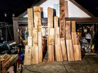
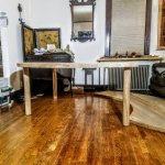
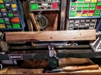
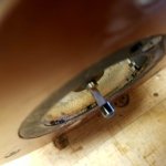
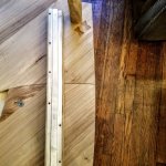
I wanted to share what I've been working on for the past few months, as I've reached a point where it's close to finished, though I have a few questions that it would be good to get some input on  Last year I built an elm table for a client that was inspired by the work of the french modernist designer Pierre Chapo, who worked largely in elm wood and has a couple of signature design elements like the visible spline joint and the cylindrical legs.

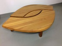
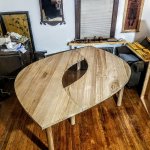
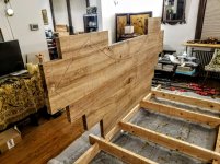
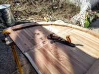
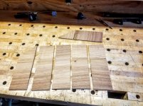
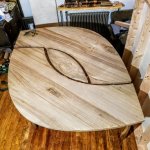
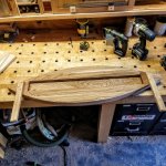
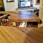
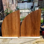
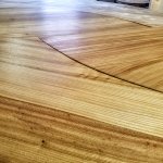
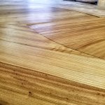
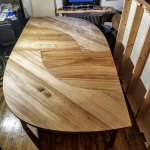
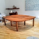
On the basis of that table I got another commission from the same architect/designer for another client to do a massive extending dining room table modeled on one of Chapo's most distinctive pieces, the T22 aka The Eye Table

[attachimg=1]

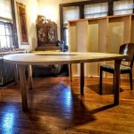
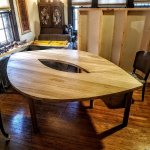
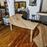
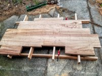
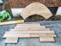
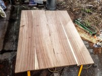
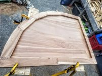
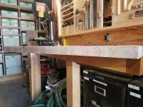
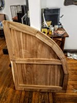
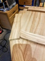
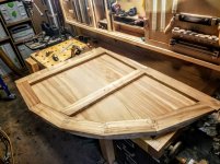
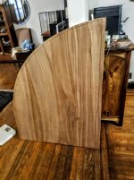
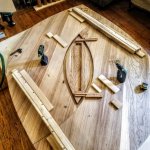
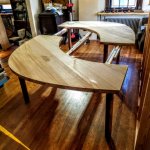
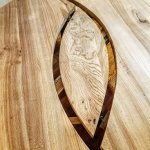
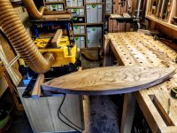
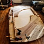
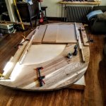
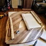
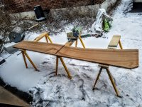
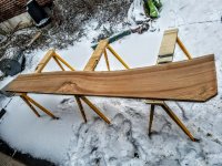
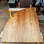
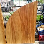
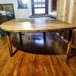
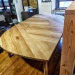
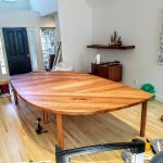
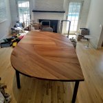
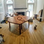
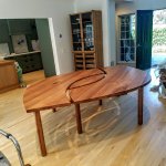
The original is a low coffee table.  What they wanted to build was a full size dining table which unextended is about 7' x 6', but with inserts shaped according to the curves would extend out to over 10 ft.

[attachimg=2]

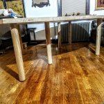
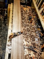
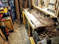
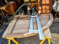
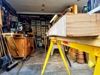
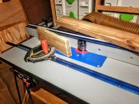
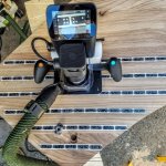
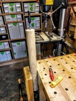
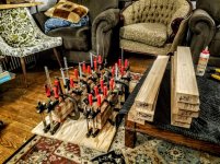
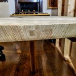
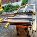
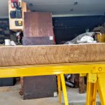
Just this morning I mounted the legs of the two main pieces and stood them up, and am planning on finishing it up this week by adding the table slides and mechanism for mounting the center pupil when the table is in its unextended position (inserts are already built).  But I wanted to do a retrospective build thread in a couple of posts, since this has been a large and at times excruciating construction process.  At the end, I will be asking some advice, so even if yiou don't feel like reading through everything, some input would be appreciated.  I'll be posting more later today and tomorrow.


Attachments

  • Chapo eye table.jpg
    Chapo eye table.jpg
    29.6 KB · Views: 1,854
  • 20200614_081339.jpg
    20200614_081339.jpg
    479.8 KB · Views: 299
  • 20200614_081327.jpg
    20200614_081327.jpg
    504.2 KB · Views: 345
  • 20200613_234939.jpg
    20200613_234939.jpg
    560.5 KB · Views: 285
  • 20200613_234912.jpg
    20200613_234912.jpg
    537.6 KB · Views: 350
  • 20200613_213430.jpg
    20200613_213430.jpg
    576.3 KB · Views: 377
  • Table design.jpg
    Table design.jpg
    39.5 KB · Views: 1,800
The closest place to me where I've found good quality thick elm boards is Berkshire Products, which is a little over 100 miles away from me in Western Massachusetts.  They mainly deal in slabs, but in the process end up producing a fair amount of rough lumber of english elm, which is the closest approximation of the wood that Chapo was using.  So I made the trip in January and basically bought them out of their quality 8/4 elm stock, to which I added a bunch of 5/4 boards to make the two table inserts:

View attachment 1

View attachment 2

I only pulled boards that were quarter or rift sawn so as to cut down on the movement of a top with so many mating curves.  The expectation was never that the different pieces would permanently mate flush, and some tolerance would have to be had for small gaps developing between the pieces over time, but the quartersawn stock would at least minimize some of that.  I actually completely exhausted the supply of long boards they had available, but was able to supplement my pile from their "shorty" bin, which saved me a bit on the total cost since this was marked down 25-50%.  Even so, the total cost was about 2500 for the whole load.

I don't know what I was thinking, but I initially set out to joint one side of the boards flat by hand (I was on a tight deadline for the table, so I guess I figured I had some time to play with).  After 3 boards I was almost swimming in a pile of wood curls

View attachment 3

View attachment 4

So I made a planing bed and did the rest with the Woodpeckers slab mill and the OF 2200

View attachment 5

With one side jointed flat, it took me the better part of a day to plane all of it to a consistent thickness on my planer. 

I then set about grouping boards to try to get an optimal grain arrangement, using templates of the final shapes that I had cut out earlier with my Shaper Origin

View attachment 6

View attachment 7

View attachment 8

The thickness of the main pieces for the top is 1.75.  Even if I had been able to score more long boards of the thicker elm, I would still have pieced the shape together from boards of different lengths as I did, rather than just gluing up one big 8x5 rectangle from boards of equal length out of which the shape would then be cut.  Had a gone the latter route, it would have become too heavy for me to manipulate.  For the inserts, making them equal in thickness to the main table would have made them too unwieldy to pop in and out, so I decided to fabricate them out of 5/4, then build up a lip around the edge to make their thickness consistent with the main table. 

To make the splines, I ended up making my own acrylic template router guide with the Shaper Origin, about which I posted a few months ago.

This made cutting the 5/8" grooves for the splines very straightforward

View attachment 9

View attachment 10

I made sure to mark on the boards the approximate point where the final edge would be, and bring the splines past that point so they would be visible when the edge was exposed.

I realize now that I might have just made the spline go the full length of the board -- my thinking was that adding a few long dominoes in the center might cut down on some of the initial cupping that the block would inevitably experience prior to resurfacing.    I was also concerned that a full length spline would make fitting the boards a hassle during the glue up, and I was mindful that any delay on such a large and complicated assembly could have really bad consequences for the seams. 

The assembly of the main pieces was probably the most arduous glue-up I've ever gone through.  I had to make a special platform to create clearance for the clamps on the underside

View attachment 11

It was pure serendipity that an old childhood friend of my wife's showed up unannounced at our place the weekend I had set to do the glue up.  He needed a place to crash for a few days, and so in exchange I got him to help me with the glue-up, which, looking back on it now, I would not have been able to execute just by myself.  The main clamps were not the problem -- it was instead the Woodpeckers Clampzillas that were the big hassle.  They work well when that is all you're using, and so form the surface on which the wood is resting.  This is what I did on the glue up for the inserts:

View attachment 12

But when instead the wood is elevated, and you have to raise up the Clampzilla to meet it, it is an absolute nightmare to get the clamps locked in place.  I had anticipated this when testing out the dry-fit, but during the actual glue-up, when we were rushing to keep within the open-time of the Titebond III, we ended up wasting an inordinate amount of time fiddling with the Clampzillas to get them in place.  But we did finally get it done:

View attachment 13

View attachment 14

Next up, I'll cover the inserts and some bad mistakes that I made that almost ruined the project.
 

Attachments

  • 20200128_195638.jpg
    20200128_195638.jpg
    486.3 KB · Views: 186
  • 20200131_192238.jpg
    20200131_192238.jpg
    481.1 KB · Views: 164
  • 20200201_153345.jpg
    20200201_153345.jpg
    560.9 KB · Views: 152
  • 20200204_112302.jpg
    20200204_112302.jpg
    437.2 KB · Views: 172
  • 20200208_170118.jpg
    20200208_170118.jpg
    502.7 KB · Views: 171
  • 20200210_205853.jpg
    20200210_205853.jpg
    450.7 KB · Views: 179
  • 20200128_144356.jpg
    20200128_144356.jpg
    525.3 KB · Views: 176
  • 20200116_105651.jpg
    20200116_105651.jpg
    483.2 KB · Views: 140
  • 20200110_144048.jpg
    20200110_144048.jpg
    470.1 KB · Views: 201
  • 20200110_190945.jpg
    20200110_190945.jpg
    106.8 KB · Views: 222
  • 20200111_182843.jpg
    20200111_182843.jpg
    584.4 KB · Views: 153
  • 20200112_000413.jpg
    20200112_000413.jpg
    605.6 KB · Views: 160
  • 20200113_215646.jpg
    20200113_215646.jpg
    497.1 KB · Views: 175
  • 20200116_105524.jpg
    20200116_105524.jpg
    550 KB · Views: 173
A very interesting build Edward... [big grin]

A lot of different things had to come together to get this baby out the door. Shaper Origin patterns, raised clamping fixtures, router fixtures, wood from the "shorty bin", the glue factory in the living room  [wink]  et al.

I'm real interested in seeing how the legs are attached and the underneath table slides. Looking forward to the rest...real nice job Edward.
 
The budget for the project was pretty generous, so we decided to farm out the final shaping of the pieces to someone with a full flatbed CNC.  I considered attempting it myself -- I was pretty confident about getting the shape right via Shaper made templates.  But the thicknessing was the hard part, or rather, getting the exact thickness on each piece, which I would have had to attempt via a large shop-made platform and the woodpeckers slab mill.  So I was happy to leave that to someone else, and could just focus on my task of getting the rough blocks ready.

Since the inserts were made out of 5/4, but had to be built up around the edges to match the thickness of the main table, I added a spline on one end of the assembly

View attachment 1

And had made the boards a few inches longer than final length so I could cut off the splined side then flip it over to book match the end that would be visible, forming a double spline

View attachment 2

I realize now that what I should have done was not do a spline on the original assembly, but rather after the glue up, run dadoes up the joints, then add in a spline that would be equal in thickness to those of the main pieces.  It's not that the double splines look bad, but they just kind of disappear when set next to the thicker, more visible splines of the main table.  But that wasn't the worst mistake on the inserts.

After cutting out the rough shape of the inserts,

View attachment 3

I built up the interior edge piece proceeding with short, angled pieces that I finger jointed to fit

View attachment 4

View attachment 5

I left an overhanging edge that I then recut slightly smaller to leave a smooth edge

View attachment 6

View attachment 7

View attachment 8

You'll see the mistake in the last pictures, which is the cross-grain battens.  I had glued them down in select spots rather than all the way across, thinking that was enough to compensate for wood expansion.  Plus I had made the inserts 2 1/4" which I though would provide enough of a buffer for the CNC to take off whatever intitial cupping did develop.

After a few days the inserts started to warp badly

View attachment 9

Realizing my mistake, I had to perform surgery with the MFS and hand tools to remove the battens:

View attachment 10

View attachment 11

View attachment 12

The CNC guy was mostly able to correct my error, but one of the inserts had warped so badly that he ended up having to bring it down to 1 1/2" to get it flat, whereas all the other pieces were at 1 11/16.

View attachment 13

I ended up building up the edge of the thinner one with some scrap I had saved from the original insert blocks, though I did have to resaw it to get enough, but it more or less matches

View attachment 15

View attachment 16

View attachment 14

View attachment 17

If I had to do it over again, I would not have even built up the interior edge.  The reason for doing so was that the inserts don't go across the entire span of the table, and so need that matched thickness to elevate them off the slides equally with the main table pieces.  But I could have just achieved the same thing by selectively blocking the inserts at those spots where they will be supported.  I think even that interior edging is continuing to mess with the wood expansion, as I've noticed a small amount of cupping even since they came back flat from the CNC -- not a lot, but it's one of the things I will have a question about in a later post.

I'll talk about the legs next.
 

Attachments

  • 20200223_112705.jpg
    20200223_112705.jpg
    555.9 KB · Views: 151
  • 20200223_160247.jpg
    20200223_160247.jpg
    497.6 KB · Views: 124
  • 20200307_164300.jpg
    20200307_164300.jpg
    384.8 KB · Views: 166
  • 20200406_172016.jpg
    20200406_172016.jpg
    114.8 KB · Views: 165
  • 20200405_153241.jpg
    20200405_153241.jpg
    454.5 KB · Views: 126
  • 20200406_163046.jpg
    20200406_163046.jpg
    458.9 KB · Views: 119
  • 20200407_104651.jpg
    20200407_104651.jpg
    377.7 KB · Views: 152
  • 20200223_103045.jpg
    20200223_103045.jpg
    532.3 KB · Views: 150
  • 20200223_101328.jpg
    20200223_101328.jpg
    437.6 KB · Views: 140
  • 20200215_094026.jpg
    20200215_094026.jpg
    396.1 KB · Views: 152
  • 20200211_130229.jpg
    20200211_130229.jpg
    96.6 KB · Views: 142
  • 20200215_102530.jpg
    20200215_102530.jpg
    300.4 KB · Views: 129
  • 20200212_172811.jpg
    20200212_172811.jpg
    422.5 KB · Views: 133
  • 20200213_090706.jpg
    20200213_090706.jpg
    411.4 KB · Views: 142
  • 20200213_091229.jpg
    20200213_091229.jpg
    413.8 KB · Views: 150
  • 20200213_095624.jpg
    20200213_095624.jpg
    458.7 KB · Views: 125
  • 20200215_093949.jpg
    20200215_093949.jpg
    399.7 KB · Views: 118
I had already come up with an effective process to do the cylindrical legs on the prior elm table build, so I was able to knock them out fairly quickly.

It involves laminating two pieces of stock, preferably from the same wider board so that they seam up along the cut line (legs were set at 3" diameter)

View attachment 1

Chuck the blocks up in the lathe to turn the rough cylinder

View attachment 2

Then build a lathe box that allows the OF 1400 to ride via a template guide slot along the top so that I could quickly cut all the legs to the same diameter

View attachment 3

View attachment 4

Then, after removing the lathe box, turn a stub on one end, change over to the chuck jaws on the headstock, add in a spindle steady and swap out the live center for a drill chuck to mill the ends for the threaded rod

View attachment 5

Tap the hole for a 12mm threaded rod, sand the interior area of the top slightly concave to aid in the fit, and  drill out the bottom for recessed table glides

View attachment 6

View attachment 8

View attachment 7

Then epoxy in the rods for security.

To attach to the top, I used these amazing threaded inserts from Misumi, which someone on the FOG told me about last year.  They are available in a variety of sizes and configurations, and most importantly, have holes so that they can be secured with screws.  They just require a carefully cut mortise to fit

View attachment 9

The inserts have enough play so that even if the rods have a bit of runout, they tighten snug to the bottom of the table, and are rock solid.

View attachment 10


Attachments

  • 20200613_213418.jpg
    20200613_213418.jpg
    191 KB · Views: 188
  • 20200613_113629.jpg
    20200613_113629.jpg
    222.9 KB · Views: 167
  • 20200310_210641.jpg
    20200310_210641.jpg
    435.2 KB · Views: 113
  • 20200308_192014.jpg
    20200308_192014.jpg
    453.3 KB · Views: 158
  • 20200225_093403.jpg
    20200225_093403.jpg
    108.3 KB · Views: 113
  • 20200222_172829.jpg
    20200222_172829.jpg
    536.6 KB · Views: 145
  • 20200218_190105.jpg
    20200218_190105.jpg
    473.1 KB · Views: 137
  • 20200218_185913.jpg
    20200218_185913.jpg
    467.3 KB · Views: 132
  • 20200218_104812.jpg
    20200218_104812.jpg
    509 KB · Views: 123
  • 20200216_232545.jpg
    20200216_232545.jpg
    539.1 KB · Views: 126
Finally got the extensions on.

This is actually the very first time I've built an extending table, and lucky me I had to figure out how to install them correctly when there isn't a single straight or parallel side on the piece.

I puzzled about this one for a while, then I finally hit upon a solution that seemed like it should work.  When fully extended, the shape of the table along the long side involves a gentle curve that peaks in the middle of each insert.  If you remove that insert, but preserve the fully extended shape, you are left with the two corners of each of the main pieces that will serve as reference points for the parallel line.

To prepare the slides I skinned them first with a thin 3/16" piece of elm on either side from the dwindling elm scrap pile I had available

[attachimg=1]

[attachimg=2]

[attachimg=3]

I attached the skin largely with 2P-10 and 23 gauge pins, only mixing in a small amount of wood glue so as not to introduce too much moisture into the wood of the slides and risk warping them.

While flush trimming the skins to the slides, I had another small victory for tool preservation -- the available lip off which to register the bearing for the flush trim bit was minimal on the top sided of the slides were the metal gears were installed.  It was too small for the bearings of the spiral or even straight bits I would normally use.  The only bit that would work was this laminate bit with an integral head that I saved from the craftsman router set that I had inherited from my grandfather.  I had tossed the router a while ago, but held on to a few of the bits, among which was this one

[attachimg=4]

With the extensions ready, I set about attaching them to the table.  Not trusting the evenness of my floor, I built a 9x5 elevated platform out of jointed 2x6s and 1/2 BB to ensure everything was level when I laid out all the table pieces.  I then made a simple jig out of plywood to align the slide off the edge, clamped down the opposite edge to preserve the spacing after the inserts had been removed, and installed the first slide:

[attachimg=5]

With that one in, then it was just a question of aligning the others via squarely cut panel material

[attachimg=6]

[attachimg=7]

That last slide in the center I installed in the closed position after checking that the table opened and closed smoothly (albeit, still lying on its back), and that the corners of the main pieces lined up.

[attachimg=8]

After blocking out the position of all the slides with scrap plywood, so that they could be taken off and put back on in the same spot, I then set about installing the pupil centerpiece.

This is the one part of the table I had done the final shaping and thicknessing myself, rather than farming it out to the CNC guy

[attachimg=9]

I just used a shaper origin made template, and the piece was narrow enough (12.5") that I could send it through the planer to match the thickness of the rest of the table.

I attached it according to the method that seems to be used in the original, which is through mating slides screwed into the piece and the table underside, so that it can be removed when extending the table and adding the inserts

[attachimg=10]

[attachimg=11]

I had to do some subsequent fine tuning to get the positioning and fit correct once the table was rightside up, but the basic mechanism appears to work well.

Yesterday I hired an assistant to help me set the table right side up.  Although they weigh over 100 lbs, up to this point I had been able to carry each of those pieces back and forth between the shop.  But since we left a slide attached on one side on each of the pieces, it would have been way too unwieldy for me to do alone, so I was happy to pay for the help.

Moment of truth came when we reattached the slides and tested out the mechanism, and praise be to God, it works.  The Osborne slides we're using work really well, in fact, and I'm able by myself to open and close the table just working from one side if I want. 

[attachimg=12]

[attachimg=13]

[attachimg=14]

[attachimg=15]

The design calls for there to be a 1 3/4 gap between all the pieces when it's in the closed position.  I set the slides so that the gap can be closed completely, but it's been requested that I add stops on the slides so that it defaults to the gapped opening so the client doesn't have to figure out on their own every time what the proper gap should be.

So now I'm working on getting the inserts lined up.  They don't lay perfectly flat, so I'm trying to come up with some tweaks so that I can get them reasonably even.
 

Attachments

  • 20200618_104544.jpg
    20200618_104544.jpg
    154.6 KB · Views: 1,139
  • 20200618_184449.jpg
    20200618_184449.jpg
    150.2 KB · Views: 1,144
  • 20200618_213043.jpg
    20200618_213043.jpg
    152.5 KB · Views: 1,165
  • 20200618_213055.jpg
    20200618_213055.jpg
    159 KB · Views: 1,160
  • 20200618_213138.jpg
    20200618_213138.jpg
    122 KB · Views: 1,157
  • 20200615_160213.jpg
    20200615_160213.jpg
    524.1 KB · Views: 1,108
  • 20200615_160213.jpg
    20200615_160213.jpg
    524.1 KB · Views: 212
  • 20200618_092212.jpg
    20200618_092212.jpg
    158.3 KB · Views: 1,154
  • 20200308_181744.jpg
    20200308_181744.jpg
    375 KB · Views: 1,204
  • 20200615_171157.jpg
    20200615_171157.jpg
    168.9 KB · Views: 1,224
  • 20200615_195851.jpg
    20200615_195851.jpg
    171.1 KB · Views: 1,192
  • 20200616_110123(1).jpg
    20200616_110123(1).jpg
    82.7 KB · Views: 1,190
  • 20200616_155351.jpg
    20200616_155351.jpg
    140.7 KB · Views: 1,185
  • 20200616_184419.jpg
    20200616_184419.jpg
    141.8 KB · Views: 1,173
  • 20200618_095854.jpg
    20200618_095854.jpg
    142.7 KB · Views: 1,169
  • 20200616_190025.jpg
    20200616_190025.jpg
    141.1 KB · Views: 1,154
Very unusual project with interesting problems and solutions. Great write up, although I do wish the photos were a bit bigger.
 
That's a challenging project. Great job and write up.
Few notes:
I would just use thickness planer sled in lieu of Woodpeckers rig for initial prep of stock under 12". Nothing fancy, strip of MDF, shims, hot glue.
I do complex panel glueups in stages, saves the headache and, ironically, time.
Have you considered low profile metal battens with expansion slots?
 
[member=15585]Svar[/member] Thanks.  I did consider the planer sled -- the eventual choice of the Woodpeckers slabbing set-up ended up being driven just as much by noise considerations as convenience.  I was doing a lot of the initial prep work at odd hours of the evening, and so I was able to work with the garage shop door closed, whereas when I plane long items, I can only do it by wheeling the planer out into the driveway.

For the inserts, I may end up trying the metal battens.  I already  bought some 3/4 x 3/4 metal bar stock from McMaster Carr in anticipation, though even that seems like it has some flex in it.  Part of the problem is that the inserts, in addition to a slight cupping, have developed a small twist, which I'm not sure even the metal battens will solve.  But I may end up using it for lack of another solution if some of the other tweaks don't work.

Svar said:
That's a challenging project. Great job and write up.
Few notes:
I would just use thickness planer sled in lieu of Woodpeckers rig for initial prep of stock under 12". Nothing fancy, strip of MDF, shims, hot glue.
I do complex panel glueups in stages, saves the headache and, ironically, time.
Have you considered low profile metal battens with expansion slots?
 
Really like the recessed glides and the lathe box was a slick move.  [big grin]  No problem getting each leg to be the same diameter.

How fast is the lathe turning when you're routing the legs?
 
[member=44099]Cheese[/member] The first time I did it on the table I made last year the process was pretty slow, but that's because I prepped the stock only by drawknifing off the square edges.  Working with the router I found I could only advance the depth in tiny increments before the bit started to get stressed and material tearout occured.  This time around though I did an initial turn with the spindle gouge to get the legs to around 3 1/8, so that I only had to do the last 1/8" with a router, so it went reasonably quickly.

Osmo matte finish looks great btw.

[attachimg=1]

[attachimg=2]

[attachimg=6]

[attachimg=3]

[attachimg=4]

[attachimg=5]

I'm glad I took some extra time on getting the wood right on the inserts.  I didn't initially get enough 1/4/riftsawn 5/4 stock, and so rather than piecing together one of the inserts with flatsawn boards, I went back up to the lumber yard and got some more, which allowed me to build the inserts from two long boards per piece, folded at the crosscut line so that the grain is well-matched.

[attachimg=7]

[attachimg=8]

You can see from the ground how long I've been working on this.

The built up edge on the insert that I had to take down to 1 1/2" is well-blended too, but I now see confirmation of what I mentioned before about the double spline joint being way too subtle as compared to the large splines on the main pieces.  They basically just disappear into the grain.  The one silver lining is that it disguises the irregularities in the spline placement.  Because the initial block went through some deformation after glue-up, which the CNC guy took out when flattening, the splines are not evenly centered around the middle of the edge, and in a couple of cases rise to within 1/16th from the face.  I'm hoping that this is a detail that only another carpenter would pick up.  Oh well, at least the most visible faces look good. 

Continuing to work today on getting the inserts to lay approximately flat.  We'll see how it goes. 
 

Attachments

  • 20200118_151304.jpg
    20200118_151304.jpg
    1 MB · Views: 1,012
  • 20200118_151205.jpg
    20200118_151205.jpg
    953 KB · Views: 1,030
  • 20200620_093421.jpg
    20200620_093421.jpg
    501.8 KB · Views: 1,075
  • 20200619_191243.jpg
    20200619_191243.jpg
    523.4 KB · Views: 1,025
  • 20200620_093407.jpg
    20200620_093407.jpg
    408.6 KB · Views: 1,027
  • 20200620_090000.jpg
    20200620_090000.jpg
    573.8 KB · Views: 1,032
  • 20200620_111037.jpg
    20200620_111037.jpg
    589.2 KB · Views: 1,058
  • 20200620_110952.jpg
    20200620_110952.jpg
    137.7 KB · Views: 1,051
In the home stretch (furthest piece in picture still needs additional coat of finish after in-between sanding).

[attachimg=1]

[attachimg=2]

[attachimg=3]

I reached out to the architect and the client to show them the issue we're having with the inserts, viz., due to a slight twist that has developed the pointed tip of the inserts sits slightly lower than the plane of the table.

[attachimg=4]

If I support the tip so that it's even with the surface, that then raises the curved part above the table line.

[attachimg=5]

I proposed a solution whereby tip support could be added, and then an additional mechanism that would involve maybe a threaded insert in the underside of the leaf along the curve into which a knob that was attached to the main piece would be fitted and then suck down the insert as you tightened it.  They said maybe down the road if there's additional movement, but for the moment they are willing to live with it.  The table will be in its unextended state for most of the time, and only get fitted with the leaves for larger gatherings.  I feel a bit sick that everything else on this project came together only to get sabotaged by this.  Oh well.

For safety purposes I added some pins along the outer edges of each insert.  Since there was no straight line off which to work, I made a jig with the Shaper that replicated the curves on both sides

[attachimg=6]

Added a straight through hole with the drill press (working off a line etched at the top by the Shaper), then drilled the corresponding holes

[attachimg=7]

[attachimg=8]

Now I'm just doing a few final tweaks to the pupil slides, then adding some stops to the slides so that it closes with a reveal.  Set to pack it up and deliver tomorrow.
 

Attachments

  • 20200620_194140.jpg
    20200620_194140.jpg
    1 MB · Views: 958
  • 20200620_191044.jpg
    20200620_191044.jpg
    789.5 KB · Views: 978
  • 20200620_185628.jpg
    20200620_185628.jpg
    817.8 KB · Views: 952
  • 20200620_180837.jpg
    20200620_180837.jpg
    981.3 KB · Views: 970
  • 20200620_180833.jpg
    20200620_180833.jpg
    1 MB · Views: 1,017
  • 20200620_182719.jpg
    20200620_182719.jpg
    729.7 KB · Views: 1,006
  • 20200620_182711.jpg
    20200620_182711.jpg
    803.1 KB · Views: 1,007
  • 20200620_202809.jpg
    20200620_202809.jpg
    795.4 KB · Views: 992
Delievered and installed the table today.  Honorable mention goes to my wife, who pointed out that the contrast between the white of the maple extensions and the honey-colored elm was a bit stark, so  I added some stain to the visible portions of the extensions and now they blend in perfectly.  Putting aside the leveling issue with the inserts, I am overall pretty happy with how it turned out.  The new owners of the table were as well -- I told them about some of the potential fixes for the insert issue, so we are going to wait and see if and how they continue to move in the new environment.  My sense is that they will live with it as -- the extensions are only going to be trotted out once in a while, and the table will be in its smaller form the vast majority of the time.

I didn't see this until I got it into a well lit space, but the table casts some cool shadows with that reveal.

[attachimg=1]

[attachimg=2]

[attachimg=3]

[attachimg=4]

[attachimg=5]

[attachimg=6]

[attachimg=7]
 

Attachments

  • 20200622_145954.jpg
    20200622_145954.jpg
    399.9 KB · Views: 925
  • 20200622_145942.jpg
    20200622_145942.jpg
    365.9 KB · Views: 922
  • 20200622_151025.jpg
    20200622_151025.jpg
    407.1 KB · Views: 895
  • 20200622_152017.jpg
    20200622_152017.jpg
    420.8 KB · Views: 924
  • 20200622_152028.jpg
    20200622_152028.jpg
    410 KB · Views: 966
  • 20200622_152048.jpg
    20200622_152048.jpg
    350.1 KB · Views: 900
  • 20200622_151531.jpg
    20200622_151531.jpg
    399.2 KB · Views: 911
[member=37411]ear3[/member]  very nice work Edward. That turned out beautifully. Outstanding.  [not worthy] [not worthy] [not worthy]

Ron
 
Fantastic project and write up, Edward!  Love the organic shape and the way the extensions fit.

Congratulations on a wonderful project and thanks for the detailed photos and process recap!
 
A really, really nice job Edward... [jawdrop]  [big grin]

The alignment pins were a nice touch.

I love the contrast of the color of the table against the white maple/oak floor. The focus of the room really is on the table.

The reveal light patterns are definitely a bonus round.  [cool]
 
Back
Top