Slartibartfass
Member
- Joined
- Apr 25, 2014
- Messages
- 1,086
I thought why not....? After some strong Google-Fu found the following inspiration:http://www.woodworkingtalk.com/f2/8020-aluminum-79713/#post793169
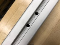
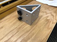
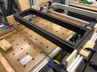
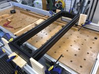
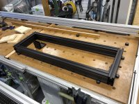
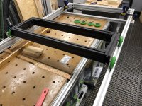
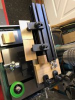
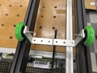
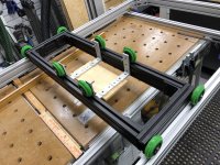
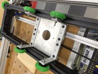
Using 2x 48” long 80-20 profiles (1515-ULS) as base attached with bolt to MFT/3.
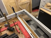
Ordered 1530-ULS profiles. The inner opening will be 93”x36”.
[attachimg=1]
[attachimg=2]
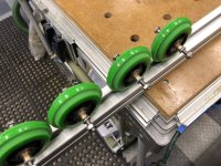
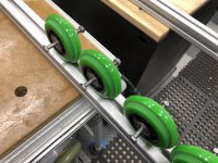
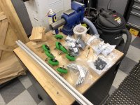
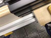
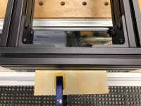
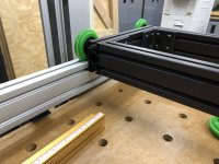
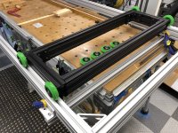
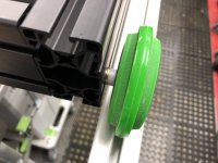
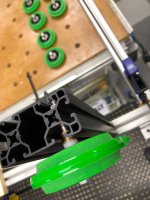
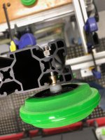
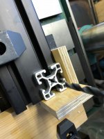
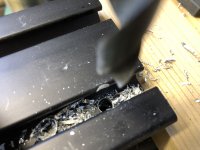
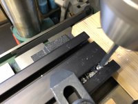
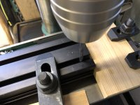
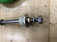
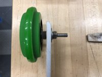
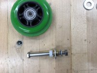
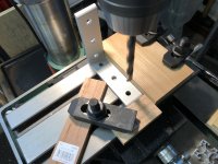
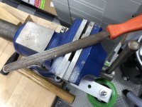
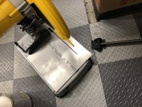
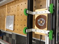
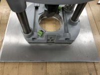
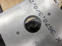
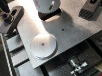
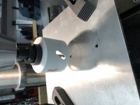
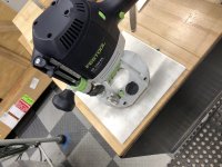
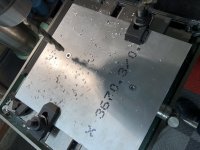
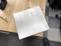
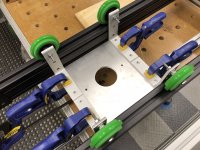
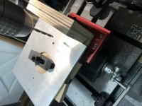
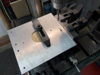
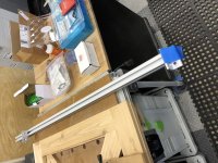
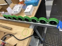
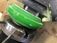
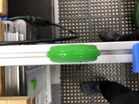
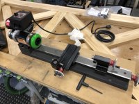
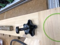
Turning the wheels for the router sled so they run in the slot of the 80-20 profile (Happy that I have the Sherline lathe (and mill.....).
[attachimg=3]
[attachimg=4]
[attachimg=5]
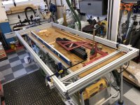
All done:
[attachimg=6]
Using 2x 48” long 80-20 profiles (1515-ULS) as base attached with bolt to MFT/3.
Ordered 1530-ULS profiles. The inner opening will be 93”x36”.
[attachimg=1]
[attachimg=2]
Turning the wheels for the router sled so they run in the slot of the 80-20 profile (Happy that I have the Sherline lathe (and mill.....).
[attachimg=3]
[attachimg=4]
[attachimg=5]
All done:
[attachimg=6]
Attachments
-
 A41A0ECF-A347-4BD7-A781-2199D9089D50.jpeg3.2 MB · Views: 75,362
 -
 B391191D-A516-4608-A3E4-5A76546689DD.jpeg3 MB · Views: 74,262
 -
 E31B7902-3191-4D7D-8025-CE5E809900EE.jpeg2.9 MB · Views: 72,948
 -
 F83A0E0E-1891-466F-8237-0D70C03EFADC.jpeg2.6 MB · Views: 72,137
 -
 2DEDC97E-2618-4E47-B2B0-C72683C7774A.jpeg2.9 MB · Views: 75,304
 -
 21612088-0DA9-4B25-B31E-FFC3A64D0CAC.jpeg2.2 MB · Views: 72,684
")