ryanjg117
Member
- Joined
- May 18, 2015
- Messages
- 329
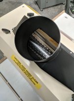
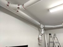
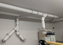
I recently installed a Clearvue CV1800 cyclone in my shop and ceiling mounting 6" duct runs. That big project is now complete, but I didn't really account for all of the time it would take to adapt my tools to accept 6" flex duct. I enjoy older machines, but sadly dust collection was an afterthought. Some machines are easier to "upgrade" than others, like my DJ-20, shown below. For this jointer, all I had to do was model a 6" dust port and ask a friend to print it on his 3D printer.
[attachimg=21]
Easy enough, look good, works good.
[attachimg=1]
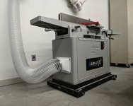
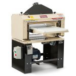
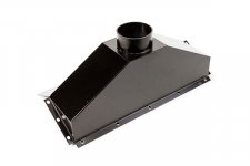
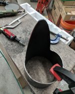
On to the planer. This is a Woodmaster W-718. A great machine featuring a removeable, heavy gauge sheet metal dust shroud.
[attachimg=2]
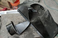
Here is a view of the shroud alone. If I screw up this project, I can always buy a replacement from Woodmaster for a measly $140.
[attachimg=3]
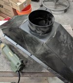
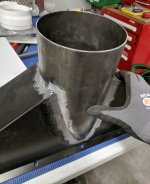
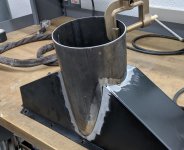
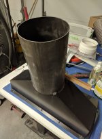
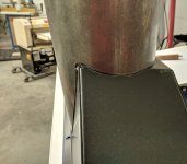
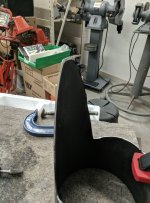
Sourcing this tube was a challenge. Initially, I purchased some 16 gauge sheet metal and attempted to bend it into a perfect cylinder with no actual metalworking or rolling tools - total failure. Next, I went on the hunt for something I could buy. I discovered it's not easy to find large diameter, thin wall metal tubing. I wanted something much thicker than your standard HVAC ducts, but not ridiculously heavy and large 1/4" thickness available from my local metal supplier. Finally, I discovered a product called ERW Tube, or electronic resistance welded tube. Available in 6" diameter with 14 gauge thickness. A little on the heavier side, but it will work just fine for this project. Here you can see me mocking it up on the dust shroud.
[attachimg=4]
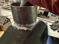
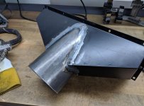
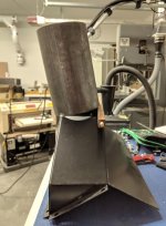
The shroud was not really designed for a exit port this large, so I had to be creative. Tilting the tube at an angle like this would allow it to fit, but result in some challenging geometry to cut and weld.
[attachimg=5]
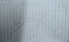
I didn't have a tool that could accurately scribe that cutting line, so I decided I would model it in CAD and print out some templates. Here, I took rough dimensions of the critical dimensions of the dust shroud.
[attachimg=6]
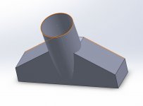
And here's a quick and dirty assembly I made in CAD, showing the two models merged. Here, you can see the challenging geometry I was eluding to earlier.
[attachimg=7]
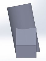
Here's a side view.
[attachimg=8]
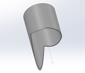
I used a cavity command to then subtract the shroud part from the cylinder part, which resulted in this part.
[attachimg=9]
Then, I did some trickeration to convert it to a sheet metal part and flatten it, providing me a pattern I could use as a template for cutting.
[attachimg=10]
Printed the template. I was lucky to have a printer capable of printing 13x19" sheets - the drawing was almost too large. I had to be careful to make sure I didn't scale the art at any time here, printing 1:1.
[attachimg=11]
After cutting the template, I wrapped it around the tube. A little short, but precise enough for this project.
[attachimg=12]
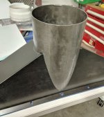
After using the template to sketch my cut lines, I went at it with a grinder and made my rough cuts to the tube.
[attachimg=13]
Here you can see me cleaning up the edges and coping them at the angle necessary for good fitment. My new favorite tool: die grinder with a quality carbide burr set. Makes quick work of cleaning up these edges and its milky smooth and satisfying to use, until you realize half of your shop is now covered in small metal shavings. Wishing I had worn a doo rag here.
[attachimg=14]
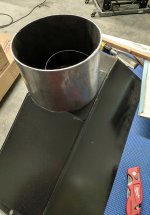
Quick test of the fitment on the dust shroud.
[attachimg=15]
Another shot of the rough fitment.
[attachimg=16]
Not perfect. Pretty good, certainly good enough to weld.
[attachimg=17]
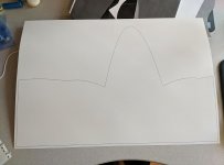
Nextup, cut the dust shroud. Here, I sketched the outline of the tube onto the dust shroud.
[attachimg=18]
Here you can see my outline.
[attachimg=22]
Cutting the shroud. I cut slightly inside my line, all around, to provide the tube something to "sit" on.
[attachimg=23]
Cutting complete.
[attachimg=24]
Cleaned up and coped the edges with a grinder and die grinder with carbide burr.
[attachimg=25]
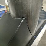
Testing the fit with both parts almost ready to be welded.
[attachimg=26]
Another shot of the test fit.
[attachimg=27]
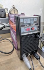
For this project, I'll be TIG welding on my new-to-me Thermal Arc ProWave 185TSW.
[attachimg=28]
Ground clamped and ready to be welded.
[attachimg=29]
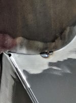
Tacked in place.
[attachimg=30]
My best looking weld of the day.
[attachimg=31]
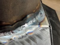
Yeah, still perfecting my TIG welding technique. Lots of stops and starts here as my torch and part ended up getting pretty hot.
[attachimg=32]
All welded up.
[attachimg=33]
Functional, if not beautiful.
[attachimg=34]
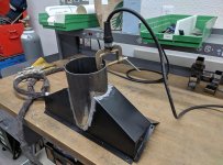
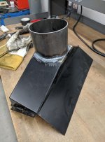
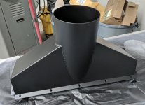
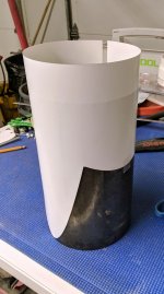
Painted in flat black and ready to be installed.
[attachimg=35]
On the machine.
[attachimg=36]
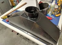
Side view, installed.
[attachimg=37]
Ready to suck chips.
And so concludes my post on a woodworking forum, featuring no actual woodworking.
[attachimg=21]
Easy enough, look good, works good.
[attachimg=1]
On to the planer. This is a Woodmaster W-718. A great machine featuring a removeable, heavy gauge sheet metal dust shroud.
[attachimg=2]
Here is a view of the shroud alone. If I screw up this project, I can always buy a replacement from Woodmaster for a measly $140.
[attachimg=3]
Sourcing this tube was a challenge. Initially, I purchased some 16 gauge sheet metal and attempted to bend it into a perfect cylinder with no actual metalworking or rolling tools - total failure. Next, I went on the hunt for something I could buy. I discovered it's not easy to find large diameter, thin wall metal tubing. I wanted something much thicker than your standard HVAC ducts, but not ridiculously heavy and large 1/4" thickness available from my local metal supplier. Finally, I discovered a product called ERW Tube, or electronic resistance welded tube. Available in 6" diameter with 14 gauge thickness. A little on the heavier side, but it will work just fine for this project. Here you can see me mocking it up on the dust shroud.
[attachimg=4]
The shroud was not really designed for a exit port this large, so I had to be creative. Tilting the tube at an angle like this would allow it to fit, but result in some challenging geometry to cut and weld.
[attachimg=5]
I didn't have a tool that could accurately scribe that cutting line, so I decided I would model it in CAD and print out some templates. Here, I took rough dimensions of the critical dimensions of the dust shroud.
[attachimg=6]
And here's a quick and dirty assembly I made in CAD, showing the two models merged. Here, you can see the challenging geometry I was eluding to earlier.
[attachimg=7]
Here's a side view.
[attachimg=8]
I used a cavity command to then subtract the shroud part from the cylinder part, which resulted in this part.
[attachimg=9]
Then, I did some trickeration to convert it to a sheet metal part and flatten it, providing me a pattern I could use as a template for cutting.
[attachimg=10]
Printed the template. I was lucky to have a printer capable of printing 13x19" sheets - the drawing was almost too large. I had to be careful to make sure I didn't scale the art at any time here, printing 1:1.
[attachimg=11]
After cutting the template, I wrapped it around the tube. A little short, but precise enough for this project.
[attachimg=12]
After using the template to sketch my cut lines, I went at it with a grinder and made my rough cuts to the tube.
[attachimg=13]
Here you can see me cleaning up the edges and coping them at the angle necessary for good fitment. My new favorite tool: die grinder with a quality carbide burr set. Makes quick work of cleaning up these edges and its milky smooth and satisfying to use, until you realize half of your shop is now covered in small metal shavings. Wishing I had worn a doo rag here.
[attachimg=14]
Quick test of the fitment on the dust shroud.
[attachimg=15]
Another shot of the rough fitment.
[attachimg=16]
Not perfect. Pretty good, certainly good enough to weld.
[attachimg=17]
Nextup, cut the dust shroud. Here, I sketched the outline of the tube onto the dust shroud.
[attachimg=18]
Here you can see my outline.
[attachimg=22]
Cutting the shroud. I cut slightly inside my line, all around, to provide the tube something to "sit" on.
[attachimg=23]
Cutting complete.
[attachimg=24]
Cleaned up and coped the edges with a grinder and die grinder with carbide burr.
[attachimg=25]
Testing the fit with both parts almost ready to be welded.
[attachimg=26]
Another shot of the test fit.
[attachimg=27]
For this project, I'll be TIG welding on my new-to-me Thermal Arc ProWave 185TSW.
[attachimg=28]
Ground clamped and ready to be welded.
[attachimg=29]
Tacked in place.
[attachimg=30]
My best looking weld of the day.
[attachimg=31]
Yeah, still perfecting my TIG welding technique. Lots of stops and starts here as my torch and part ended up getting pretty hot.
[attachimg=32]
All welded up.
[attachimg=33]
Functional, if not beautiful.
[attachimg=34]
Painted in flat black and ready to be installed.
[attachimg=35]
On the machine.
[attachimg=36]
Side view, installed.
[attachimg=37]
Ready to suck chips.
And so concludes my post on a woodworking forum, featuring no actual woodworking.
Attachments
-
 34 - Helical Head.jpg225.7 KB · Views: 1,027
 -
 35 - Jointer.jpg141.7 KB · Views: 1,172
 -
 19 - Cutting Hole.jpg286.9 KB · Views: 1,169
 -
 20 - Hole is Cut.jpg171.1 KB · Views: 1,168
 -
 21 - Hole is Cleaned Up.jpg185.1 KB · Views: 1,064
 -
 22 - Final Test Fit.jpg285.3 KB · Views: 1,072
 -
 23 - Another Shot of Test Fit.jpg193.6 KB · Views: 1,110
 -
 24 - TIG Machine.jpg325.8 KB · Views: 1,086
 -
 25 - Assembly Put Together.jpg206 KB · Views: 1,070
 -
 26 - Tacked in Place.jpg187.1 KB · Views: 1,092
 -
 27 - Close Up of Tack.jpg179.4 KB · Views: 1,085
 -
 28 - Weld Bead.jpg180.3 KB · Views: 1,116
 -
 29 - Weld Beads.jpg255.4 KB · Views: 1,032
 -
 30 - Weld Beads.jpg192.1 KB · Views: 1,027
 -
 31- Painted.jpg147.1 KB · Views: 1,059
 -
 32 - Installed.jpg275.7 KB · Views: 1,101
 -
 33 - Installed.jpg181.4 KB · Views: 1,104
 -
 19 - Cutting Hole.jpg286.9 KB · Views: 222
 -
 18 - Tracing Negative.jpg193.4 KB · Views: 242
 -
 18 - Tracing Negative.jpg193.4 KB · Views: 1,061
 -
 00 - Woodmaster W718.jpg558.4 KB · Views: 1,204
 -
 01 - Standard Dust Chute.jpg15.9 KB · Views: 1,179
 -
 02 - ERW Pipe.jpg205.2 KB · Views: 1,186
 -
 03 - ERW Pipe at Angle.jpg200 KB · Views: 1,164
 -
 04 - Dust Shroud Sketch.jpg94.4 KB · Views: 1,130
 -
 05 - 3D Model 1.jpg36 KB · Views: 1,183
 -
 06 - 3D Model 2.jpg15 KB · Views: 1,140
 -
 07 - 3D Model 3.jpg23.9 KB · Views: 1,073
 -
 08 - 3D Model 4.jpg25.6 KB · Views: 1,214
 -
 09 - Template Printed.jpg107.5 KB · Views: 1,117
 -
 17 - Test Fit 4.jpg191.3 KB · Views: 1,061
 -
 16 - Test Fit 3.jpg202.8 KB · Views: 1,070
 -
 15 - Test Fit 2.jpg253.6 KB · Views: 1,079
 -
 14 - Test Fit 1.jpg246 KB · Views: 1,088
 -
 13 - Coping the Cut.jpg2 MB · Views: 1,075
 -
 12 - Tube Cut.jpg335.8 KB · Views: 1,075
 -
 10 - Wrapped Template.jpg284.2 KB · Views: 1,170
 ...absolutely love