TSO Parallel Guide not accurate

metafor

Member
Joined
Dec 11, 2023
Messages
2
I'm trying to use my TSO parallel guides for a larger panel (24" x 48"). What I've noticed is that I can calibrate the two parallel guides at 10" and using a combination square, I confirmed that the two guides were at 10".

However, after I move the guides to 24" (both on the 24" mark), I see that one of the guides is off by about a 1/16" compared to the other guide. Anyone had this experience and have any advice on what could be wrong?
 
So I went through a whole world of pain with my TSO guides when I first got them. However, I was unlucky enough to have brand-new Festool rails and a square that was out.

So my advice is to check these first. After I changed rails, I really enjoy the system.
 
I find the lines on the TSO guides too thick for 1/16 accuracy. You have to be very consistent to match both sides to the same side of the line.

Their YouTube video kind of shrugs it off that you should not be stressing out to such accuracy levels when woodworking.

Personally I think it's a bit unfortunate. They have a very nice product and thinner lines with the magnifying crosshair would be a fantastic match.

 
usernumber1 said:
I find the lines on the TSO guides too thick for 1/16 accuracy. You have to be very consistent to match both sides to the same side of the line.
...
I think too many people see the TSO PGs (actually any PGs) as a panacea while completely missing the purpose of parallel guides.

These things are about repeatability. If one makes one cut, then resets, then another cut, then resets, then ... one is missing the point/advantage of (any) parallel guides. In such a workflow one can as well just mark and place the rail. That would be way cheaper and produce a similar, possibly even a better result.

Sure, sure. The TSO v2 Flipstops are excellent vis-a-vis the alternatives. But these are still "just" visual stops. They can ever "be" only as accurate as the eye (and the experience) of the user.

If you need absolute precision, then you need a reference piece. Period. No one's eye is ever gonna be
 
Total sidetrack however Peter Millard had a great tip for obtaining accurate cuts without PGs.


This technique shines when using a story stick.

I used to sell the Rip Guide PGs, which were a pre-TSO setup using Incra tracks, like many others. To this day I struggle to hit a consistent 1mm accuracy when resetting the stops. I'd agree that the real benefit to PGs is repeatability.

RMW
 
As user#1 says the increment marks are too wide for precise adjustment and as mino says they should only be considered as a rough guide. Use something physical to set the flag to. And unless you’re making multiple cuts at the same setting don’t bother with any parallel guides.

That said, compare the increments on each rail to a precision rule and if they are not close, return one or both.
 
Sorry mino I dont agree with any of that. The guides are are not repeatable to each other. You cannot set the left one to be same as the right one using the printable lines.

Yes there are other methods to set them but those are workarounds and time consuming. I would expect to use the lines on the product itself primarily.

The festool guides as crude as they are have very precise lines but the crosshair is too big. The easy fix is to use a paolini square or some other ruler/square extension to have the crosshair precise as well. And it works quite well.
Sadly it's much harder to fix the lines on the TSO as they add a variation in thickness among other things
 
Thanks all. Wow, that's quite disappointing. I understand that I can't expect absolute (1/32") precision from just looking at the markings but...I didn't expect that one rule would vary so much against another rule. If I put both at the same marking, I wouldn't expect 1/16" of a difference.

Something to be aware of. And of course, the reason I'm using guides is for repeatable cuts.

One question I have is why the PG's don't auto-square on the rails. I use a large precision square to square them against the back of the rail before tightening the knobs. But it seems like that should be done ahead of time.
 
metafor said:
I'm trying to use my TSO parallel guides for a larger panel (24" x 48"). What I've noticed is that I can calibrate the two parallel guides at 10" and using a combination square, I confirmed that the two guides were at 10".

Hello metafor,
we can help you resolve the Parallel puzzle you describe if you will email us directly with your phone number, please,
to: info@tsoproducts.com
Flag your email "attention Hans" thus creating a record of the entire email exchange.

Your report suggests that there is a dimensional error creeping that is not inherent to the design but could be a non-conforming components in the entire resolution process.

We will help you clear that up!

Hans

PS: we cannot monitor the FOG PM system or text meassages on the phone.

 
usernumber1 said:
I find the lines on the TSO guides too thick for 1/16 accuracy. You have to be very consistent to match both sides to the same side of the line.

I've always had the same issue and consistently setting both guides to the same number was always a problem. A few years ago I removed one of the stainless flag stops and polished it to reflect the laser markings. For me, it helped make the basic/quick adjustment process easier, although nothing short of thinner laser markings and a magnifying cursor will improve the overall accuracy.

[attachimg=1]

[attachimg=2]

[attachimg=3]
 

Attachments

  • 7322.JPG
    7322.JPG
    332.7 KB · Views: 605
  • 7325.JPG
    7325.JPG
    229.3 KB · Views: 606
  • 7326.JPG
    7326.JPG
    734.7 KB · Views: 607
mino said:
...
Yep. One thing to note - one should never use the center but the "edge/boundary" of any mark to measure. That makes the thickness irrelevant, as long as it is consistent. That is why I never understood the idiots who sell tape measures where the main centimeter (or inch) marks are wider than the mm scale marks.
...

[member=61691]TSO_Products[/member]
Please take this note to your engineering:

I did not notice it before, but it seems your laser etching is done the wrong way - the marks for "main" scale are wider (not only longer which is correct) than the ones for the detailed scale. This is fundamentally wrong per above quote of mine. It prevents (consistently) using the edge of the marking for a readout which is the engineering best practice for these types of scales where max precision is needed.
Effectively this forces one to account for this by a guesstimate or one needs to calibrate the guides twice for precision -> once for using the whole-inch and whole-centimeter marks which are wider and the second time (ca 1/128" moved) for the small scale distances.

Also having the color a bit darker to improve the contrast may help, same with the cursor not being white-ish stainless but a blackened one etc. But the width of the major and minor scales not being the same is the main problem here in my view. And a relatively easy one to fix at that.
 
i understand you mino i just dont agree

the TSO parallel guide as they are named to me are an acronym for parallelogram guides. a hairline crosshair with a hairline mark would not be having these issues.

the polishing trick is quite neat i like that.

edit: parallelogram is wrong sorry. they are good at making trapezoids(?) i think i got it right. one side longer
 
I use two matching aluminum yard sticks to measure the cut.  I do have to remember to add 1/8” to the measurement (something I have failed to do a couple of times).

I have meant to epoxy a bit of aluminum to the ends to eliminate the need to remember.  I never seem to get around to do it. 

If I am making a single cut, I will use these rulers instead of mounting the two squaring arms. 
 
usernumber1 said:
i understand you mino i just dont agree

the TSO parallel guide as they are named to me are an acronym for parallelogram guides. a hairline crosshair with a hairline mark would not be having these issues.

the polishing trick is quite neat i like that.

edit: parallelogram is wrong sorry. they are good at making trapezoids(?) i think i got it right. one side longer
Fair.

Then I do not trully do not understand the complain - maybe a photo of the problem you see with some marked notation ?

ADD:
Cheese's photos are from the side, so they are not illustrative as one never measures a scale from the side - so they do not help on this. Can you possibly take a photo from *your eyes* perspective where you see the markings problem ?

The only thing I can imagine that would correspond to your note is if the edges of the laser markings were trully horiibly jagged on your set - which I find hard to believe.  As I noted to Cheese, the thickness o the mark is irrelevant if the mark read-out is done correctly by referencing the boundary of the mark. Only the consistency, and, possibly, the cleannlines of its mark edge is what matters for a good read out. That and the contrast, but that is more of a skill to a big part than a property of a scale.
 
woodbutcherbower said:
I have absolutely no idea what 1/16th or 1/32nd of an inch actually looks like. Not a clue.
Ok, for me:

1/32" => 1 mm, i.e. way off

Eye markings are up to about 0.5 mm cummulative accuracy (aka 1/64" in americanese) when two errors, each of 0.2mm are put together.

The PGs and in general the FS/2 + TS system can do repeatability up to about 0.1 mm error (roughly 1/256"), with about 0.2mm achievable in most cases. *)

*) With Makita tracks having a bit lower straightness standard, that goes to about twice as bad - 0.2 mm tops / 0.4 mm usual as the practical accuracy achievable.

[member=61691]TSO_Products[/member]
Something went wrong with my previous post, so will retry but shorter:

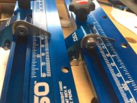
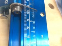
From photos by Cheese it seems your current etching is done such the "major scale" marks are different width than the "minor scale" ones. This is wrong as it prevents referencing the edge of the mark - as is the engineering best practice when accuracy is concerned.

When multiple scales are used, the "major" scale can use longer marks, but they must not be wider. Right now, when the user calibrates, in effect if doing it right he has to calibrate differently depending if the major scale is to be used or the minor scale. That is not good. And is pretty easy to fix.

And what is even worse is the variable-width etching guides the user to (try) reading the center of the mark instead of the edge of it. Which is the worst possible scenario for accurately precisely reading a scale.
 
mino said:
1/32" => 1 mm, i.e. way off
25.4mm in one inch.
so 1/32" is < 1mm.
It doesn't change the point you're trying to make. I only point it out because you seem to really value things being correct. :)

mino said:
accurately precisely
Nice to see someone using those words correctly, especially considering it's your second? language. :)
 
alltracman78 said:
25.4mm in one inch.
so 1/32" is < 1mm.
It doesn't change the point you're trying to make. I only point it out because you seem to really value things being correct. :)
Actually, that was conscious and intentional.

In engineering, any construction design for that matter, I believe the most important is to understand the importance of an error "scale" and assign it a proper significance, not so much its absolute value.
In that way, one does not bother with 0.32 versus 0.254 but may want to bother with 0.4 versus 0.2 differences at one place, or completely ignore - if within the acceptable deviation of that situation.

I do try "lead by example" over here. In "precision talks" among non-engineers, it is all too easy to get lost in absolutes. So so easy to waste energy on solving non-existent problems, lacking it later to solve the real ones.

Nice to see someone using those words correctly, especially considering it's your second? language. :)
Well, physics is my first language really ... shall feel ashamed having used the wrong term to begin. To my defence, in (colloquial) czech there is only one word used for both, the meaning derived from context. Nudges a person to do the same in other languages ..
 
Back
Top