Tutorial for accurately measuring something?

rmwarren

Member
Joined
Jul 11, 2010
Messages
3,063
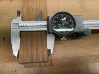
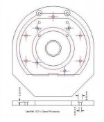
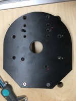
Can anyone recommend good tutorials or resources to learn the skills to accurately measure something like a router base plate? The goal is to develop the skills needed to take something existing, like the base plate, and do a precise take-off of the various feature that can then be reproduced in CAD or otherwise.

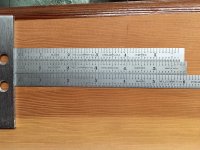
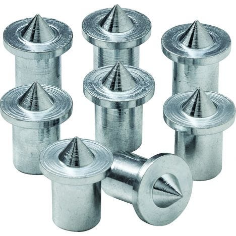
A corollary to this is anything related to doing accurate layouts when creating stuff, i.e. techniques for layout lines, center punching, fixturing, etc. What I think I'm looking for are the skills of an old-time tool & die maker from pre-CAD/CNC times. I'm already searching Tom Lipton's YT channel but wondered if there are more focused resources.

I'll actually use this for a router base plate but I'm looking for some general education on how to do it properly in whatever scenario I run into.

Thanks,

RMW

 
Richard,

Don't have a CNC but have made many router plates. My standard procedure is to use cone-point setscrews in the tapped holes in the router to mark the hole locations, this works very well. I normally find the center of the blank and drill a 1/4" hole in that location. With a piece of 1/4" drill rod in the collet. I slide the blank over the rod until it's sitting on the tips of the setscrews  - a couple of gentle taps with a mallet and I have centerpunches at the hole locations. If you want to expand the procedure, grind a point on the drill rod and use that to mark the collet center. To get measurements for making the baseplate, install the setscrews and the pointed dowel (use a piece of clear acrylic sitting on the points to set them to the same projection so you get uniform/minimal punch marks) , set the router on top of a piece of smooth posterboard and tap the end of the router - you'll wind up with punch marks at the collet and hole locations. Using the punch marks, a straight edge and a sharp pencil, connect the punch marks and you can now measure the dimensions between the various holes. Very low tech, but it works.

PS Been using your parallel guides a lot recently, working out well for me. Thanks.

Tom
 
If you find more resources, please share them. 

But I think the most expedient way will ultimately be transfer punches, like tomp said
 
Richard, I've always just done this the old fashioned way...measuring & marking using a good calipers and a couple of Starrett fully flexible stainless rules.

[attachimg=1]

[attachimg=2]

The Starrett rules are small, thin & flexible so they can fit in a lot of tight spaces. I also really like them for the hundredths increments so that the measurements I take are easily read and aren't being confused or inverted. The hundredths on the rules also play nicely with the thousandths on the caliper.  [smile]

I prefer to locate items off of hard stops so to locate the center of a hole, I'll use a dowel pin, transfer punch or even a drill bit placed in the hole to measure its location.

Metal radius gauges also come in handy or even plastic circle templates that a draftsman used to use work well.

For marking centers I use a scribe with a point as sharp as a needle for the smallest marking. 

All dimensions are transferred to a cad program, a 1:1 drawing is printed and the drawing is compared to the original parts to make sure everything is in correct order. 

Make sure the printer is actually printing at 1:1 by putting a 10" line on the paper, making a print and then measuring the length of the line.

It's a slow process but if enough care is taken the result will be within a few thousandths of the original parts.

Here I took dimensions from a OF 1400 router base and an OF 1010 router base and merged the dimensions so that I could mount either router up to a Micro Fence router rail guide.

[attachimg=3]

And here's the machined plate, OF 1010 denoted with yellow dots & OF 1400 denoted with red dots.

[attachimg=4]
 

Attachments

  • 2951.JPG
    2951.JPG
    788.4 KB · Views: 569
  • 6541.jpg
    6541.jpg
    1.2 MB · Views: 517
  • 5932.JPG
    5932.JPG
    30.2 KB · Views: 549
  • 5931.JPG
    5931.JPG
    2 MB · Views: 518
Yes, I agree just sit down with a pair of calipers and carefully measure everything out. transfer punches work to if the material being used to guide the punch is thick enough. If its thin than transfer punches wont help much. Flat head screws will help measure hole centers since they will want to self center then measure out to out and minus one screw diameter will get you c-c just measure everything and dont assume a 1/4 screw is .250. Pre cnc I would sometimes print out the cnc drawing and spray glue the paper right to the work. no need to get crazy on the spray glue just light dusting on one side and tack it down. If its a finished surface you can put masking tape down first. 
 
For something like a router base, I'd put it on the scanner bed along with a 6" ruler. Scan it, import into your vector designer of choice, then use the ruler to ensure the scale is correct. After that, you can drop lines, circles, whatever else in a vector layer that is over the scanned image. Makes it so easy.
 
You are looking for a basic course in mechanical design, when I was in engineering school half a century ago that was about 20% of the freshman year curriculum.  The best way to approach this in general is to have your dimensional analysis parallel the fabrication that it will inform.  So think about the first cut you would make on a workpiece, that would be a major datum for things parallel to it.  Then you might do a second cut to form a side perpendicular to the first cut.  That becomes a major datum for things parallel to it.  The location of the centers of holes are a pair of coordinates measured from these first two sides.  It is best practice to dimension as many entities in the workpiece from these two major axes rather than dimensioning entities from other entities as the errors will accumulate rather than be direct to the primary reference.  Features that are dimensioned along radii like the mounting holes for a router plate start from a center located to the two primary datums and angles plus radii from the center to locate the hole centers.  When you specify a hole to accommodate a fastener the ID of the hole should be larger than the OD of the fastener such that the error tolerance in the fastener hole location will still allow the fastener to be installed.  So for example if you have a 1/4" bolt going through a hole and the location of the hole is +/- 1/32" then a 5/16" hole located in the tolerance zone will allow the bolt to be installed without interference. 
 
Cheese said:
Richard, I've always just done this the old fashioned way...measuring & marking using a good calipers and a couple of Starrett fully flexible stainless rules.

[attachimg=1]

[attachimg=2]

The Starrett rules are small, thin & flexible so they can fit in a lot of tight spaces. I also really like them for the hundredths increments so that the measurements I take are easily read and aren't being confused or inverted. The hundredths on the rules also play nicely with the thousandths on the caliper.  [smile]

I prefer to locate items off of hard stops so to locate the center of a hole, I'll use a dowel pin, transfer punch or even a drill bit placed in the hole to measure its location.

Metal radius gauges also come in handy or even plastic circle templates that a draftsman used to use work well.

For marking centers I use a scribe with a point as sharp as a needle for the smallest marking. 

All dimensions are transferred to a cad program, a 1:1 drawing is printed and the drawing is compared to the original parts to make sure everything is in correct order. 

Make sure the printer is actually printing at 1:1 by putting a 10" line on the paper, making a print and then measuring the length of the line.

It's a slow process but if enough care is taken the result will be within a few thousandths of the original parts.

Here I took dimensions from a OF 1400 router base and an OF 1010 router base and merged the dimensions so that I could mount either router up to a Micro Fence router rail guide.

[attachimg=3]

And here's the machined plate, OF 1010 denoted with yellow dots & OF 1400 denoted with red dots.

[attachimg=4]

The transfer punch is probably all you need to make an accurate router baseplate.  For those who have never used one, the work exactly like dowel centers do:
42341-01-1000.jpg


Transfer punches come in sets:
PUNCH_SET-3_noBG-1.png


All you need to do is to clamp the old base to the new stock and trace the outer shape.    Then use the appropriate size transfer punch to mark the centers of the holes you intend to use.  No measuring involved.  Then cut out the blank and drill the holes. 
 
Back
Top