120V Sys Power Box

Bohdan said:
Just a question to those that have done the mod.

Are you replacing the builtin thermal cutout because at 240v the sys can supply 2500w but at 120v this will drop to 1250w before the overload pops.

An interesting point as this is the label inside the PowerHub.

Look at the coiled vs uncoiled rating.
 

Attachments

  • 5141.jpg
    5141.jpg
    706.8 KB · Views: 856
Bohdan said:
Just a question to those that have done the mod.

Are you replacing the builtin thermal cutout because at 240v the sys can supply 2500w but at 120v this will drop to 1250w before the overload pops.

I’d like to understand this better or explore it further.  Not an expert but have some electrical experience.

Watts are the unit of power - P = I x V

My understanding is the power (watts) will remain essentially constant at 240V vs 120V, only the amperage will vary.

I believe a given Festool will draw some number of watts - whether it’s running on 120 or 240V.

If the thermal cutout is based on watts (this part I’m not sure of) won’t it be exactly the same - the wattage draw is constant, just the combination of current and voltage will vary?

If so won’t the thermal cutoff be the same?  Or I’m missing something.

 
jdm5 said:
I’d like to understand this better or explore it further.  Not an expert but have some electrical experience.

Watts are the unit of power - P = I x V

My understanding is the power (watts) will remain essentially constant at 240V vs 120V, only the amperage will vary.
 

In theory, correct.  The reality varies by the power factor of the device.  P = I x E x (power factor)

jdm5 said:
I believe a given Festool will draw some number of watts - whether it’s running on 120 or 240V.

If the thermal cutout is based on watts (this part I’m not sure of) won’t it be exactly the same - the wattage draw is constant, just the combination of current and voltage will vary?

If so won’t the thermal cutoff be the same?  Or I’m missing something.

A thermal cutoff interrupts a circuit when it reaches a pre-set temperature.  The design criteria will tell you what the critical factors are for the device.  Generally, the specification calls for a cutout at a specific temperature caused by exceeding a specific current draw measured in amps.  Both can vary based on design criteria
.
 
Bohdan said:
From the looks of the pics of the power box Festool actually use a resetable one as nothing would have gotten hot.

The non resetable type is used when the tool has to cool down from overheating so that it doesn't let out the magic smoke such as in the TS55. If they had one in the Kapex there wouldn't a regular requirement for new armatures.

Ah, I see now. I neglected to refer to an image that shows the other side/external-face of the cutout. You're right, it's clearly the resettable kind (it even includes the domed clear plastic "waterproof" screw-on cover that protects the reset button). Good to know. Thanks for setting me straight. I've circled in red the relevant bits in Greg's images for anyone else who may be confused:

[attachimg=1]

[attachimg=2]
 

Attachments

  • inside_socketcompressed.jpg
    inside_socketcompressed.jpg
    29.2 KB · Views: 1,912
  • SYSPH Thermal Cutout ExternalCompressed.jpeg
    SYSPH Thermal Cutout ExternalCompressed.jpeg
    27 KB · Views: 2,060
Interesting discussion, thanks all.

For those who have done the mod, what can you realistically plug in vs. not?  I’d like to figure out real-world usage before jumping in myself. 
 
So, in putting together a parts list for my 'DIY-sys-ph', I'm encountering difficulty finding what I would refer to as "busbars". I know that I could simply wire everything together with wire nuts and a rat's nest of wire but I like the clean look produced by a bus bar. Moreover, given the knocks and vibration a power distribution tool box would be subjected to, it just makes sense to follow the kinds of electrical connection practices that are employed in the stock SYS-PH. 

Therefore, I figure I will either need one bus bar capable or handling all three functions (hot, neutral, ground) or three, one each for the hot, the neutral and the ground. Whatever it/they would look like, it/they would need to permit an adequate number of connection points for five outlets and an indicator light).

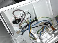
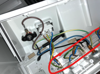
Looking at the guts of the SYS-PH (and also being familiar with the guts of a common 120V AC power strip) it's clear to me that each employs a similar looking busbar (or 'power distribution bar' or 'terminal block bus bar'?), the SYS-PH version of which is circled in red below:

[attachimg=1]

Pretty simple - the hot, neutral and ground wires plug into one end and take-offs emerge when necessary from the relevant bar to attach each outlet to the busbar.

The trouble is that no amount of searching produces anything that looks like it would be appropriate for a 120V 15A AC system.

I can find examples of busbars intended for DC systems - like overkill-quality bus bars for marine use (which look like what I imagine a bus bar should look like):

71CCjsihzpL._SL1410_.jpg


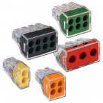
...and other less-beefy versions for automotive use as well as busbars intended for residential (though low-voltage) uses - like this one - but I can't find anything that looks remotely like the busbar in the SYS-PH nor anything at all that looks like it would work for spreading ~1600W-2200W loads across five NEMA 5-15 outlets and a small 120V LED indicator light. At this point, I'm thinking that I am not using the proper terminology in my searches.

Any ideas?
 

Attachments

  • SYSPHBusbar.png
    SYSPHBusbar.png
    775.3 KB · Views: 2,391
Just a heads up.  This thread is likely going to be be split.  The original part of the thread was about taking a systainer - a plastic box - and then adding off the shelf electrical components.  The second part of the thread is about modifying a Festool electrical product.

Peter
 
Peter Halle said:
Just a heads up.  This thread is likely going to be be split.  The original part of the thread was about taking a systainer - a plastic box - and then adding off the shelf electrical components.  The second part of the thread is about modifying a Festool electrical product.

FWIW Peter, if you split this thread, consider naming one thread SYS-PowerHub and the other one Sys Power Box to differentiate between the actual Festool product and a home grown product.  [smile]
 
TinyShop said:
So, in putting together a parts list for my 'DIY-sys-ph', I'm encountering difficulty finding what I would refer to as "busbars".

Any ideas?

Keep it simple...lever nuts.  Rated voltage - 400, rated current 32A.  They’re all I use now b/c they enable  easy unit serviceability in the future and the wires won’t shake loose.

44c6bb7671a997ce4605815e12d2fb9d.jpg


Edit:  Wago is the brand I use - Wago 222-415 LEVER-NUTS 5 Conductor Compact Connectors 40 PK by Wagohttps://www.amazon.com/dp/B0195V2LX8/ref=cm_sw_r_cp_api_f3vNAbC1V0VW7
 
Scorpion said:
Keep it simple...lever nuts.  Rated voltage - 400, rated current 32A.  They’re all I use now b/c they enable  easy unit serviceability in the future and the wires won’t shake loose.

44c6bb7671a997ce4605815e12d2fb9d.jpg

Good call on the Wago connectors, easier and safer than anything else.  [thumbs up]  Too bad they don't come in a 6-wire model for this application. However, a 5-wire and 3-wire used together would work. [smile]
These can also be mounted on a DIN rail using their mounting carrier.
http://www.heilind.com/products/wago/wago_Lever_nuts_222_series.asp

Just ran across the new version of the older 222 connector, now known as the 221 connector. These should be easier to use than the 222 series because the push down lever is a lot larger. [smile]
http://www.wago.us/media/us/collection/brochures/221_2016.pdf

Which brings up an alternative for this application. I use 6-wire Wago Wall Nuts for outdoor lighting. I use standard 14 ga outdoor wire which is stranded. I just tin the ends and insert it into the Wago connectors. These are available for up to 8-wires and can also be mounted on a DIN rail.
 

Attachments

  • Wago-Push Wire Wall Nuts.jpg
    Wago-Push Wire Wall Nuts.jpg
    55.4 KB · Views: 644
[member=27782]Scorpion[/member] & [member=44099]Cheese[/member] - Thanks so much for the advice!

Having recently emerged from the rabbit hole of learning from scratch about DIN rails and terminal blocks (oh my!), I now feel a little more equipped to move ahead with my DIY-sys-power-box. Although I now understand that I could assemble three busbars using sets of single-layer, 2-pole terminal blocks connected by jumpers, I'll stick with the even simpler method (that you so thoughtfully suggested) of using three 8-conductor Wall Nuts, the combination of which will provide me with a total of 24 positions (a.k.a "connection points"). Since one position per "Wall Nut" will be occupied by the respective line wire (hot, neutral or ground) this will leave seven positions free and available for connecting the various wires that will attach the outlets, the indicator light and the thermal cutoff. After everything is connected, I'll be left with one free position on each of the hot and neutral Wall Nuts and two open positions on the ground Wall Nut (in each case, just enough for future expansion possibilities).

While I'd have preferred Lever Nuts (easier to remove wires once installed should that ever become necessary) I was put off by the need to install jumper wires between the three sets of 5-conductor and 3-conductor Lever Nuts (as you no doubt understood, I'd need to combine them in this manner in order to achieve enough open positions for the number of wires I'll be working with. So, needlessly complex.

Also, for a more stable build, I will purchase a 12" length of 35mm aluminum DIN rail, two Wago screwless DIN rail end stops and two Wago Fixing Carriers (the latter of which will allow the Wall Nuts to snap onto the DIN rail). I'll fasten an appropriate length of DIN rail to the floor of the systainer (using pop rivets and washers or maybe I'll glue a piece of plywood to the floor and use screws to mount the DIN rail to it).

Either way, I like the idea of using Wall Nuts as impromptu (and inexpensive!) busbars and am very appreciative to have been pointed in their direction.

So, my final parts list (w/sources and pricing) is comprised of the following:
  • One (1) gently-used bright yellow T-Loc II systainer, US$54.95 (picked up on eBay for free using accumulated eBay bucks);
  • Leftover 12/3 indoor Romex (I'll remove the outer sheath and use the remaining strands individually to wire everything to the makeshift busbars);
  • A short length of old 12/3 extension cord (that includes the male plug);
  • Some offcuts which I'll use as nailers (I'll attach them as necessary to the walls and floor of the systainer, likely using PU glue);
  • Some leftover luan or other thin ply (which I'll use to close-in the electronics);
  • Leftover hi-temp crimp terminal ends (for attaching wires to the integral spade connectors on the receptacles, indicator light and thermal cutoff);
  • Five (5) 5-15 IP54 receptacles, US$34.95 (purchased for free using accumulated eBay Bucks);
  • 12" of aluminum DIN rail, US$5.95 (purchased for free using accumulated eBay bucks);
  • One (1) 120V LED indicator light, Red (plus 1 as spare), US$12 (purchased for free using accumulated eBay Bucks);
  • One (1) 120V 15A Thermal Overload Switch, Resettable (plus one spare), US$6.53 (purchased for free using accumulated eBay Bucks);
  • Three (3) Wago 773-168 8-conductor "Wall Nuts", purchased for the whopping sum of US$0.295/each (plus shared shipping) here
  • Two (2) Wago 773-332 Fixing Carriers, purchased for the whopping sum of US$0.318/each (plus shared shipping) here; and
  • Two (2) Wago Screwless End Stops, purchased for US$1.35/each (plus shared shipping) here;
In the end, total build cost will be US$10.23 (basically the cost of the order from Newark). I challenge anyone to do it for less! ;)                       
 
Moderator Note

This thread started out as a DIY project using a Systainer and then installing electrical items.  Later it turned into a thread about about modifying a Festool Sys-Hub.  The policy of the forum is to not allow posts about modifying Festool products.

There may appear to be gaps in the thread above.  Unfortunately some posts have been removed.

PLEASE do not post about electrically modifying Festool products.

Peter Halle - moderator
 
The forum guidelines allow descretion for the evaluation of posts.  You can certainly review them.  Modifying Festools electrically and then posting here would be an excellent example of what ANY manufacturer would not want on their own forum.

Peter
 
As a follow up to my last post, I specified electrically modifying because this was a thread that was talking about just that.

Peter
 
How about a previous post where a member modified a Festool router to add LED lighting to it, would that also be a no no?
 
The rules are clear but clearly not enforced in all situations.  I’m a grown man and fully understand the consequences of modifying tools and equipment.  In this case we’ve discussed replacing outlets with OEM replacement parts and doing so would require nothing more than basic electrical skills similar to what’s necessary to add the second plug to a dust collector (which Festool willingly sells to me) or change out a factory plug on a non-Festool with a plugIt connector (I have 10).

I will concede but I do so in protest.  I’m a rule follower but this one feels like it’s landing on the wrong side of the line.

Edit:  it’s so simple I think Festool should sell a conversion kit BTW.

Edited Again:  I think that when tools are purchased from companies outside of the US and shipped or carried into the US, we should call it “The Green Market”

Sent from my iPhone using Tapatalk Pro
 
TinyShop said:
[member=27782]Scorpion[/member] & [member=44099]Cheese[/member] - Thanks so much for the advice!

Having recently emerged from the rabbit hole of learning from scratch about DIN rails and terminal blocks (oh my!), .....                     

Did you ever build this project with the DIN rail. If so it would be fun to see a picture or two of the finished product.
 
Greg Powers said:
TinyShop said:
[member=27782]Scorpion[/member] & [member=44099]Cheese[/member] - Thanks so much for the advice!

Having recently emerged from the rabbit hole of learning from scratch about DIN rails and terminal blocks (oh my!), .....                     

Did you ever build this project with the DIN rail. If so it would be fun to see a picture or two of the finished product.

I'm currently traveling but fully intend to post detailed project notes upon my return (July'ish). All of the individual components are at home, just waiting to be assembled. FWIW I do my best planning away from home when I have the time to spend researching and mentally designing. Stay tuned! :)
 
Great thread here!  I have been looking at options for power distribution at a rolling stack that could include chargers as well.  [member=44099]Cheese[/member]  You mentioned that you were going to put your CSX charger in the empty space of your box.  Do you have a pic of that?  I am curious how much space is left for another charger.  I have a Milwaukee M12 charger I would also add in the box if it would fit.

The conversion looks like a winner!  Great job guys! :D
 
Back
Top