newoldwoodworker
Member
- Joined
- Jan 10, 2020
- Messages
- 22
I didn't find anything on the Internet showing the inside of Rolair's Airstak, and I bought one recently so I'm hoping this is useful information for anyone thinking of getting one. Though I haven't used it yet on a job, my current job's still at demolition stage, I've run it through some test work, and it's been fantastic so far. I bought Cadex 18 gauge and Cadex 23 gauge nailer/pinner at the same time, and its performance seems perfect for that. I'm not planning to use it for anything larger than my 18 gauge, and its capacity seems perfectly suited for that purpose.
Getting to the point of this post... I seem to be someone who can't leave "good enough" alone, so I sorta tore mine apart. One of the reasons for this is that mine arrived with the gauge faces recessed at least 1/2" deep behind the green insert panel. That made it difficult to see the gauges, so I wanted to fix that. Second, I couldn't easily turn the pressure adjustment knob and didn't want to break it, so I wanted to figure out if there was a lock engaged (there wasn't; It was just very stiff and needed some initial screwing & unscrewing to loosen it up.) I took a few photos along the way, of parts I thought were interesting. If there's anything else someone's interested in, please let me know and I'll go do that too. In the process, I added some inexpensive closed-cell carpet pad foam beneath the unit, between the metal base and the Systainer. That made a noticeable difference to the tone of the pump, and perhaps made it a bit quieter.
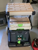
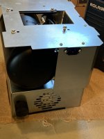
The whole compressor is built in a sheet metal frame that is simply placed down into a fairly standard Sys 4 Systainer. There are cutouts on one side for the motor's fan exhaust and for the power cable. (Mine came with a 6' cable, by the way, not 4' as in a popular review video). There is enough space for the power cable, but not enough for a 25' air hose. I am thinking of replacing the Sys 4 with a Sys 5 so I can store everything together.
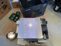
Here's the unit resting right-side up, outside its Systainer, with the motor's cover panel partially removed. In order to lift out the unit, the green panel with cutouts needs first to be unclipped from the front of the Systainer. The clips are molded into the green part, so unclipping can be done with a plastic wedge and a little persuasion.
View attachment 1
And here's a view of the motor and compressor:
View attachment 2
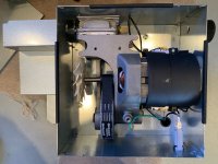
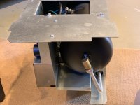
Flipping the unit upside down, we can see the tank, tank condensate drain, the (male C13) power connector, and the motor's fan.
View attachment 3
On my unit, the screws holding the tank to the base have been installed into holes that are about 3/4" back from the other set. This goes partway to explaining why my gauges were too far recessed behind the green panel. Later I discovered that moving the screws to the front set of holes fixed the gauges so they were at least flush with the panel, but then the front side of the motor cover wouldn't allow the Systainer cover to close. (I later decided to sacrifice part of the Systainer cover reinforcement, sanding that down so I could read the valves.)
There were even marks looking like the screws had originally been placed in the other set of holes. At this point I was thinking maybe the Airstak is really more of a prototype-level production volume, and Rolair is still figuring out how they're going to fit this thing.
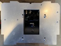
A more clear view of the base:
View attachment 4
Spinning the unit 180 degrees, and still upside down, we see the pump's tube feeding the tank, and a pressure gauge of the front setup.
View attachment 5
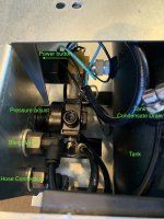
Looking down into that rectangular opening in the base, the power and regulator components are visible:
View attachment 6
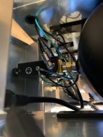
Then, turning the unit right side up, and spreading open the panel that wraps the side for the power switch, here's that part and the actuator valve:
View attachment 7
I hope these photos are helpful. I recently saw an Airstak on display at Woodcraft store near me. Its gauges weren't recessed, so maybe I just got an oddball. I'm too impatient to have sent mine back, and I was more inclined to take it apart and "fix it".
Peter
Getting to the point of this post... I seem to be someone who can't leave "good enough" alone, so I sorta tore mine apart. One of the reasons for this is that mine arrived with the gauge faces recessed at least 1/2" deep behind the green insert panel. That made it difficult to see the gauges, so I wanted to fix that. Second, I couldn't easily turn the pressure adjustment knob and didn't want to break it, so I wanted to figure out if there was a lock engaged (there wasn't; It was just very stiff and needed some initial screwing & unscrewing to loosen it up.) I took a few photos along the way, of parts I thought were interesting. If there's anything else someone's interested in, please let me know and I'll go do that too. In the process, I added some inexpensive closed-cell carpet pad foam beneath the unit, between the metal base and the Systainer. That made a noticeable difference to the tone of the pump, and perhaps made it a bit quieter.
The whole compressor is built in a sheet metal frame that is simply placed down into a fairly standard Sys 4 Systainer. There are cutouts on one side for the motor's fan exhaust and for the power cable. (Mine came with a 6' cable, by the way, not 4' as in a popular review video). There is enough space for the power cable, but not enough for a 25' air hose. I am thinking of replacing the Sys 4 with a Sys 5 so I can store everything together.
Here's the unit resting right-side up, outside its Systainer, with the motor's cover panel partially removed. In order to lift out the unit, the green panel with cutouts needs first to be unclipped from the front of the Systainer. The clips are molded into the green part, so unclipping can be done with a plastic wedge and a little persuasion.
View attachment 1
And here's a view of the motor and compressor:
View attachment 2
Flipping the unit upside down, we can see the tank, tank condensate drain, the (male C13) power connector, and the motor's fan.
View attachment 3
On my unit, the screws holding the tank to the base have been installed into holes that are about 3/4" back from the other set. This goes partway to explaining why my gauges were too far recessed behind the green panel. Later I discovered that moving the screws to the front set of holes fixed the gauges so they were at least flush with the panel, but then the front side of the motor cover wouldn't allow the Systainer cover to close. (I later decided to sacrifice part of the Systainer cover reinforcement, sanding that down so I could read the valves.)
There were even marks looking like the screws had originally been placed in the other set of holes. At this point I was thinking maybe the Airstak is really more of a prototype-level production volume, and Rolair is still figuring out how they're going to fit this thing.
A more clear view of the base:
View attachment 4
Spinning the unit 180 degrees, and still upside down, we see the pump's tube feeding the tank, and a pressure gauge of the front setup.
View attachment 5
Looking down into that rectangular opening in the base, the power and regulator components are visible:
View attachment 6
Then, turning the unit right side up, and spreading open the panel that wraps the side for the power switch, here's that part and the actuator valve:
View attachment 7
I hope these photos are helpful. I recently saw an Airstak on display at Woodcraft store near me. Its gauges weren't recessed, so maybe I just got an oddball. I'm too impatient to have sent mine back, and I was more inclined to take it apart and "fix it".
Peter
Attachments
-
 Unit_outside_systainer.jpeg163.1 KB · Views: 509
 -
 motor_compressor.jpeg161.8 KB · Views: 480
 -
 Tank_motor_fan_power_C13male.jpeg114.1 KB · Views: 473
 -
 base_tank_drain.jpeg127.3 KB · Views: 327
 -
 pump_to_tank_inlet.jpeg152.3 KB · Views: 314
 -
 components_underside_labled.jpeg137.3 KB · Views: 364
 -
 power_switch-activator_valve.jpeg124.4 KB · Views: 351
")