My first post here, inspired by the excellent precision jig shared by user ‘Ola C’. A version of which I built and have already used for picture framing projects. The additional accuracy of the Ola C jig has made it my go to item for any small piece domino work. I’ve also found that hand pressure (as opposed to setting clamps) is often sufficient to keep parts in place while using the domino, greatly speeding up repetitive work.
My alternative solution for precision domino work, makes use of a Festool MFT dog hole layout, the parf guide system (v1) and the domino cross stop accessory.
This jig is probably best explained in pictures, but some explanatory notes below.
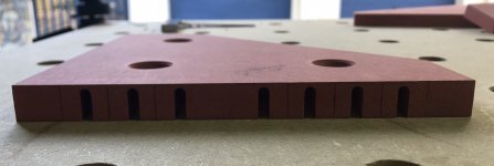
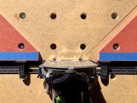
- The angle setting jigs x2 (orientated 45 or 90 degree as required) are secured on the MFT table using dogs.
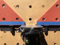
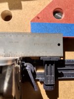
- The DF500 is positioned relative to the workpiece, using location pin holes (cut into the angle setting jigs) for the cross stop jig.
- The location pin choice and cross stop measurement are transferred from left to right jig (or right to left) when the opposing face dominos are cut.
- The jigs also act as a squaring face of the domino main body or cross stop locating pin faces. I note that the cross stop faces are not exactly aligned with the DF500 main body face (estimate 1mm short). I therefore position the left and right jigs to ensure I use either the DF500 face or the two cross stop faces to square to the workpiece. Otherwise there is the opportunity for slight misalignment.
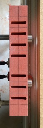
- I lightly clamp the cross stop jig to the MFT table using screw clamps. This ensures squareness to workpiece when making cut. This is a clumsy solution and something more elegant is required.
Additional notes:
- The angle setting jig dog holes are cut using the parf guide system.
- 45 and 90 degree cuts on the jigs are made using the parf dog + rail clip system. This is important since the angles need to be referenced to the MFT hole layout pattern.
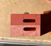
- Cross stop pin location holes were made using the domino DF500 (5x30 cutter). I clamped both jigs together when making the cut to ensure the pin locations are perfectly mirrored on both LH and RH jigs. Made cut with widest domino setting. This ensures a >10mm slot hight, that aligns with the cross stop pin height.
- The jigs are cut from 16mm Valchomat. A jig from thicker material would be better to allow for higher placed dominos. I intend making one from 30mm Valchromat as a next iteration. You could easily place a spacer sheet under the DF500+cross stops for higher positioned dominos. There may be some complication cutting the cross stop pin location holes with thicker material if using the process from note above.
- The UJK wedge system proved to be very efficient for clamping. Also used the bessey MFT toggle clamps successfully. Screw clamps are a pain.
[attachimg=1]
[attachimg=2]
[attachimg=3]
[attachimg=4]
[attachimg=5]
[attachimg=6]
[attachimg=7]
[attachimg=8]
[attachimg=9]
Hope this is of interest and use the community!
My alternative solution for precision domino work, makes use of a Festool MFT dog hole layout, the parf guide system (v1) and the domino cross stop accessory.
This jig is probably best explained in pictures, but some explanatory notes below.
- The angle setting jigs x2 (orientated 45 or 90 degree as required) are secured on the MFT table using dogs.
- The DF500 is positioned relative to the workpiece, using location pin holes (cut into the angle setting jigs) for the cross stop jig.
- The location pin choice and cross stop measurement are transferred from left to right jig (or right to left) when the opposing face dominos are cut.
- The jigs also act as a squaring face of the domino main body or cross stop locating pin faces. I note that the cross stop faces are not exactly aligned with the DF500 main body face (estimate 1mm short). I therefore position the left and right jigs to ensure I use either the DF500 face or the two cross stop faces to square to the workpiece. Otherwise there is the opportunity for slight misalignment.
- I lightly clamp the cross stop jig to the MFT table using screw clamps. This ensures squareness to workpiece when making cut. This is a clumsy solution and something more elegant is required.
Additional notes:
- The angle setting jig dog holes are cut using the parf guide system.
- 45 and 90 degree cuts on the jigs are made using the parf dog + rail clip system. This is important since the angles need to be referenced to the MFT hole layout pattern.
- Cross stop pin location holes were made using the domino DF500 (5x30 cutter). I clamped both jigs together when making the cut to ensure the pin locations are perfectly mirrored on both LH and RH jigs. Made cut with widest domino setting. This ensures a >10mm slot hight, that aligns with the cross stop pin height.
- The jigs are cut from 16mm Valchomat. A jig from thicker material would be better to allow for higher placed dominos. I intend making one from 30mm Valchromat as a next iteration. You could easily place a spacer sheet under the DF500+cross stops for higher positioned dominos. There may be some complication cutting the cross stop pin location holes with thicker material if using the process from note above.
- The UJK wedge system proved to be very efficient for clamping. Also used the bessey MFT toggle clamps successfully. Screw clamps are a pain.
[attachimg=1]
[attachimg=2]
[attachimg=3]
[attachimg=4]
[attachimg=5]
[attachimg=6]
[attachimg=7]
[attachimg=8]
[attachimg=9]
Hope this is of interest and use the community!
Attachments
-
 IMG_5798.JPG974.2 KB · Views: 2,164
 -
 IMG_1562.JPG563.1 KB · Views: 2,018
 -
 IMG_8894.JPG523.6 KB · Views: 2,093
 -
 IMG_1488.JPG194.8 KB · Views: 1,963
 -
 IMG_1218.JPG452 KB · Views: 1,936
 -
 IMG_7935.JPG474.2 KB · Views: 2,053
 -
 IMG_2270.JPG445.5 KB · Views: 1,893
 -
IMG_3323.jpg450.5 KB · Views: 202
-
IMG_3323.jpg450.5 KB · Views: 167