Best way to put keyholes on board edge OF 1400

Welshdog

Member
Joined
Dec 1, 2010
Messages
51
Howdy,

I want to put four keyholes (I have a bit for this) on the back edge of a shadowbox style shelf that I am building. With the right wall anchors, this will allow the shelf to be mounted flush to the wall. The boards are 3/4" thick so there is plenty of width for the bit.  I'm trying to figure out the best way to do this.  The Festool plexi Template Routing Aid is too expensive - I'm a hobbyist and this sort of job will be infrequent.  I know folks sometimes use two Parallel Edge Guides, but again, $82 for four holes is a bit steep.

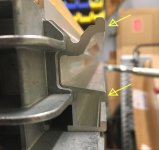
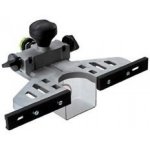
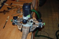
I'm trying to set up the MFT with a rail and the router guides and the board clamped to the edge of the table.  I have the Table Widener installed on the router. This looks like it should work, but it also seems a bit awkward.  Not 100% sure, but I think I see a slight misalignment of the router plate to the top of the board.  Pondering this.

Am I missing something here?  Is there a better way to put keyholes in board edges?

Thanks!
 
You can clamp a 2x4 flush on each side to balance the router on, then use an edge guide on just one side.

You could set another clamp to limit the top height so they are identical.
 
I am just making sure I understand your situation correctly.

Your workpiece is clamped to the outside edge of the MFT.  The narrow side (3/4") is facing up.  You have leveled the top of the work piece to the top of the MFT.  You are now setting up your guide rail (not attached to any MFT hardware) to allow you to route keyholes.

Are you trying to route the keyhole slots to run along the length of the board (install your finished workpiece and then slide it sideways to lock in place) or hang (vertically place your workpiece)?

Peter
 
Peter Halle said:
I am just making sure I understand your situation correctly.

Your workpiece is clamped to the outside edge of the MFT.  The narrow side (3/4") is facing up.  You have leveled the top of the work piece to the top of the MFT.  You are now setting up your guide rail (not attached to any MFT hardware) to allow you to route keyholes.

Yes this is correct.  I used two dogs to position the rail straight to the table edge, and then clamped the rail - not using MFT hardware.

Are you trying to route the keyhole slots to run along the length of the board (install your finished workpiece and then slide it sideways to lock in place) or hang (vertically place your workpiece)?

Peter

Keyholes are oriented along the board length and it will be a vertical, drop down to hang, installation.
 
Peter_C said:
You can clamp a 2x4 flush on each side to balance the router on, then use an edge guide on just one side.

You could set another clamp to limit the top height so they are identical.

That's a good idea.  Adding to the pile.  Thanks.
 
So I did use the rail and guide stops to cut the keyhole slots - it worked pretty well and the results are good.  Keyholes are now ready.

I did learn something interesting.  The MFT side rails have an issue that I will describe.  The side rails have the v-groove element for clamping the protractor down.  Below that there is the standard channel seen on the guide rails that accepts the Festool clamp foot. See picture.  As best I can tell the upper v-groove element sticks out just a fraction more than the clamping element below it.  Thus when you clamp a board to an outer rail, it will not be 90º perpendicular to the top.  It's is of course possible that my MFT top is distorted/sagged, but I got the same results all the way around with two different squares.  It also could be something out of whack in how the MFT parts are bolted together.  I've never taken the MFT apart, but I did flip the top once.

Anyone else ever noticed this?  I don't think it's a big deal, it just gave me a bit of trouble with this particular task.  I shimmed the board to the bottom extrusion element with some hard plastic sheeting and that got it close to square with the top.
 

Attachments

  • rail.jpg
    rail.jpg
    1,003.5 KB · Views: 516
I have the older 1080 & 800 MFTs, and they also exhibit a similar issue with the side profiles not being plumb. With these older models, the corner pieces are to blame. And, this is most likely to be the issue with your newer MFT/3.
 
Thanks - good to know.  I wonder if there is a technical reason why they don't mill down that top extrusion element to create a clamping surface square to the top?  Seems like it would make the table all the more useful.
 
Welshdog said:
So I did use the rail and guide stops to cut the keyhole slots - it worked pretty well and the results are good.  Keyholes are now ready.

I did learn something interesting.  The MFT side rails have an issue that I will describe.  The side rails have the v-groove element for clamping the protractor down.  Below that there is the standard channel seen on the guide rails that accepts the Festool clamp foot. See picture.  As best I can tell the upper v-groove element sticks out just a fraction more than the clamping element below it.  Thus when you clamp a board to an outer rail, it will not be 90º perpendicular to the top.  It's is of course possible that my MFT top is distorted/sagged, but I got the same results all the way around with two different squares.  It also could be something out of whack in how the MFT parts are bolted together.  I've never taken the MFT apart, but I did flip the top once.

Anyone else ever noticed this?
I just checked my old 2015 and a 2018 (NIB that I just unpacked today) MFT/3 for what you described:
My machinist square square (25/10 cm) makes contact with both the V-groove and the T-nut part when being flush on the top surface everywhere, except on the back of the right-side rail of the old one where the end of the long leg has ~1/4mm air to the top when making contact with both V+T parts of the rail - I can live with that.

In case someone can't:
Looking at how the rails are mounted it should be quite straightforward to loosen the screws, put a shim between them and the corner blocks (at the upper or lower screw, depending on the tile one wants to correct) and re-tighten the screws to set the contact points of the rails square to the top.
 
Back
Top