ear3
Member
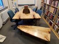
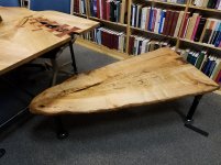
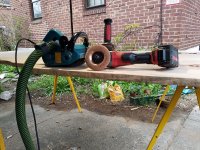
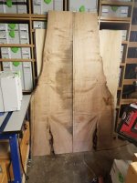
Finally getting around to these bookmatched spalted maple slabs -- purchased last March during Boards and Beams' (Fairfield, NJ) 2-for-1 slab sale -- that have been standing in the corner of my dining room for over a year. They are being turned into a conference table for my office.
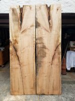
View attachment 1
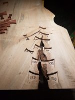
Starting dimensions were around 28" x 100" x 1.75". When I got them though I planned on removing the sharkfin in the lower half that you can see in the picture resulting from a massive split in the left slab (mirrored with marker on the right). There was simply no way a table in excess of 48" all the way down was going to work for the space, and that size would have made the assembly and maneuvering very difficult in the one man shop I run.
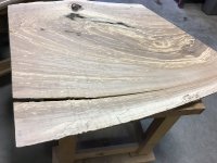
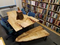
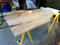
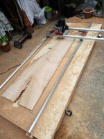
So I worked with jig saw and tracksaw to pare down the slabs to this, with the wide part at 24" and the narrower going down to 12":
View attachment 2
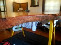
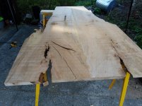
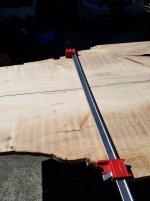
I took off perhaps too much on the length, reducing them to around 81", but I was dealing with significant bowing along the length on both of the slabs, and additional length would have sacrificed even more thickness. As it was I ended up having to remove almost a 1/2" from both to flatten the stock with the Woodpeckers slab mill, working off a 10' 2x6 and ply frame I built for the process:
View attachment 3
Final thickness came out at 1.25" -- a tad thinner than I was originally hoping for, but the loss of material is compensated for by the reduced strain on my back when moving the completed, lighter table top.
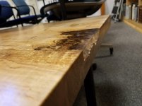
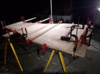
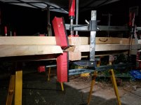
After jointing the glue edge on both with the TS75 + standard blade and domino-ing them with 12x140mm dominoes, I set about the task of joining them. This was definitely a challenging glue up owing to 1) the lack of a 90 degree outside edge for over half of the seam; 2) the split at the top, where applying clamping pressure to the outer edge would likely crack the crotch; and 3) the presence of softer, spalted wood along part of the edges that risked deformation under clamping pressure.
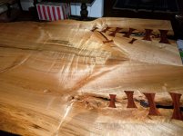
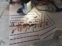
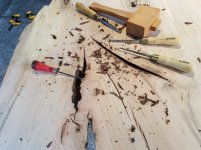
I solved the first problem by simply jigsawing a series of pockets at regular clamping points that ran parallel to the joint:
View attachment 4
The slabs as purchased didn't have a full live-edge, so creating the pockets did not ruin any integrity I was trying to preserve.
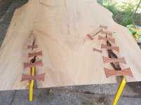
I worked around the second problem by affixing scrap wood clamping blocks on the interior of the split on both sides of each slab. I initially just used a mix of screw Clamps and 2p10 to keep the blocks in place, but after they started to fail under the clamping pressure of the Bessey parallel clamps, I said screw it and screwed them in place as well, figuring a few more holes in the slabs wouldn't stand out among all the other splits and knots I was going to have to epoxy anyway:
View attachment 5
View attachment 6
This ended up working, though just barely. There's a hairline seam visible along the last few inches of the joint -- small enough that a normal person won't pick it up, but of course my eye still gets stuck on it every time I inspect the surface.
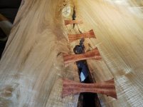
The third problem proved more vexing, and there was definitely some deformation at a couple of clamping points from the tremendous force of the I Beam clamps.
View attachment 7
I ended up having to jig saw some of this away after it was all said and done.
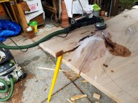
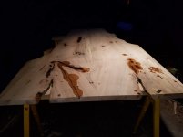
Combined slab after glue-up in preparation for an initial rough sand with the Rotex150:
View attachment 8
View attachment 9
Followed by a flat sanding up to 100 grit with the RS2.
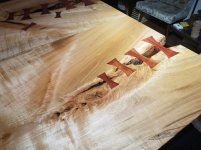
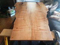
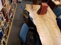
I then took a step which I wish I could take back, which was to jig saw along the non-parallel edges to remove the clamping pockets, taking off about an inch on both sides (in addition to more substantial portions where the spalted wood had cracked). What I should have done is simply worked from the beginning with the tools I used at the end to simulate a live edge, which was a coarse kutzall shaping disc and the makita wheel sander:
View attachment 10
Not a huge deal, but I lost a couple of inches in width on the final product.
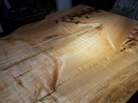
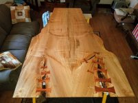
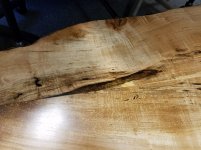
Next I set about cleaning and filling with epoxy all the splits and other deformities, sanding down with the RAS after they had dried:
View attachment 11
View attachment 12
View attachment 13
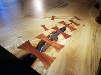
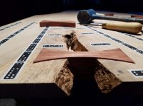
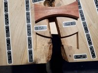
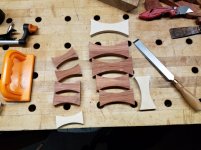
Next up, the butterfly inlays.
View attachment 1
Starting dimensions were around 28" x 100" x 1.75". When I got them though I planned on removing the sharkfin in the lower half that you can see in the picture resulting from a massive split in the left slab (mirrored with marker on the right). There was simply no way a table in excess of 48" all the way down was going to work for the space, and that size would have made the assembly and maneuvering very difficult in the one man shop I run.
So I worked with jig saw and tracksaw to pare down the slabs to this, with the wide part at 24" and the narrower going down to 12":
View attachment 2
I took off perhaps too much on the length, reducing them to around 81", but I was dealing with significant bowing along the length on both of the slabs, and additional length would have sacrificed even more thickness. As it was I ended up having to remove almost a 1/2" from both to flatten the stock with the Woodpeckers slab mill, working off a 10' 2x6 and ply frame I built for the process:
View attachment 3
Final thickness came out at 1.25" -- a tad thinner than I was originally hoping for, but the loss of material is compensated for by the reduced strain on my back when moving the completed, lighter table top.
After jointing the glue edge on both with the TS75 + standard blade and domino-ing them with 12x140mm dominoes, I set about the task of joining them. This was definitely a challenging glue up owing to 1) the lack of a 90 degree outside edge for over half of the seam; 2) the split at the top, where applying clamping pressure to the outer edge would likely crack the crotch; and 3) the presence of softer, spalted wood along part of the edges that risked deformation under clamping pressure.
I solved the first problem by simply jigsawing a series of pockets at regular clamping points that ran parallel to the joint:
View attachment 4
The slabs as purchased didn't have a full live-edge, so creating the pockets did not ruin any integrity I was trying to preserve.
I worked around the second problem by affixing scrap wood clamping blocks on the interior of the split on both sides of each slab. I initially just used a mix of screw Clamps and 2p10 to keep the blocks in place, but after they started to fail under the clamping pressure of the Bessey parallel clamps, I said screw it and screwed them in place as well, figuring a few more holes in the slabs wouldn't stand out among all the other splits and knots I was going to have to epoxy anyway:
View attachment 5
View attachment 6
This ended up working, though just barely. There's a hairline seam visible along the last few inches of the joint -- small enough that a normal person won't pick it up, but of course my eye still gets stuck on it every time I inspect the surface.
The third problem proved more vexing, and there was definitely some deformation at a couple of clamping points from the tremendous force of the I Beam clamps.
View attachment 7
I ended up having to jig saw some of this away after it was all said and done.
Combined slab after glue-up in preparation for an initial rough sand with the Rotex150:
View attachment 8
View attachment 9
Followed by a flat sanding up to 100 grit with the RS2.
I then took a step which I wish I could take back, which was to jig saw along the non-parallel edges to remove the clamping pockets, taking off about an inch on both sides (in addition to more substantial portions where the spalted wood had cracked). What I should have done is simply worked from the beginning with the tools I used at the end to simulate a live edge, which was a coarse kutzall shaping disc and the makita wheel sander:
View attachment 10
Not a huge deal, but I lost a couple of inches in width on the final product.
Next I set about cleaning and filling with epoxy all the splits and other deformities, sanding down with the RAS after they had dried:
View attachment 11
View attachment 12
View attachment 13
Next up, the butterfly inlays.
Attachments
-
 20190407_172909.jpg567.7 KB · Views: 299
 -
 20190421_102329.jpg669.8 KB · Views: 202
 -
 20190418_194617.jpg284.9 KB · Views: 194
 -
 20190417_182054.jpg534.5 KB · Views: 198
 -
 Faux live edge.jpg312.5 KB · Views: 235
 -
 20190417_172816.jpg680.3 KB · Views: 210
 -
 20190417_172650.jpg610.6 KB · Views: 227
 -
 Spalting split.jpg210.5 KB · Views: 162
 -
 20190412_173343.jpg204.1 KB · Views: 193
 -
 20190413_174153.jpg300.9 KB · Views: 240
 -
 20190416_145401.jpg163.3 KB · Views: 175
 -
 20190416_210419.jpg466.1 KB · Views: 212
 -
 20190416_210541.jpg482.6 KB · Views: 187