Classic Systainer Foot Template

Scorpion

Member
Joined
Jan 15, 2014
Messages
587
I made a template for cutting reliefs into shelving for t-loc feet using patterns from a previous thread on FOG.  I haven’t been able to find patterns for the classic systainers.  Does anyone know where to find them? 

TIA

Sent from my iPhone using Tapatalk Pro
 
Here is what I saved a while back.
 

Attachments

  • Systainer dimensions I-IV.jpg
    Systainer dimensions I-IV.jpg
    20.2 KB · Views: 6,840
Can you share your T-lock Systainer foot template, Matt?  SVG or PDF with dimensions would be great!

thanks -

neil
 
neilc said:
Can you share your T-lock Systainer foot template, Matt?  SVG or PDF with dimensions would be great!

thanks -

neil

[member=167]neilc[/member] I am going to create one soon, using Easel from Inventables and let you know how it fit in a T-Loc systainer

Mario
 
neilc said:
Can you share your T-lock Systainer foot template, Matt?  SVG or PDF with dimensions would be great!

thanks -

neil

Here’s one I’ve had for a while.  I have another I’m still looking for.  I’ll post it as soon as I find it.

bfa1fa9d4920097410a959994e6718d6.jpg


Sent from my iPhone using Tapatalk Pro
 
I’ll post dimensions at some point but here’s what I came up with.   

6e35d4174d2a94ccd56b5f37ef3abeaf.jpg


The feet require square corners so they’re not as fast to cut with a router and teleplay as the t-locs.  After cutting I had to square the edges with a chisel.  Will work just fine though, they retain the systainer the same way as the others.

57a766e0e1cd4becf2b26308132c8fe5.jpg


Sent from my iPhone using Tapatalk Pro
 
I ended up finding the one I used to make my T-Loc template from.  Turns out it was pinned in Pinterest. 

a76b6dd77fd800c5d2cf3333f2fbad9d.jpg


Sent from my iPhone using Tapatalk Pro
 
[member=167]neilc[/member] oops I forgot about that one. Here the link for the inventables project T-Loc Systainer Insert. If you don't want to worry about inventables I can send you the toolpath file (.nc).
 
Don T said:
Here is what I saved a while back.

  It was a long time ago that I did those drawings.  [wink]  Not a foot template though.  Here are the rest ----------------------------

Systainer - I  Details

[attachimg=1]

--------------------------------------------------------------------------------------------------------------------
Systainer II - V  Details

[attachimg=2]

---------------------------------------------------------------------------------------------------------------------

[attachimg=3]

[attachimg=4]

Seth
 

Attachments

  • Systainer - I details.jpg
    Systainer - I details.jpg
    62.8 KB · Views: 8,286
  • Systainer II - V details.jpg
    Systainer II - V details.jpg
    93.6 KB · Views: 8,237
  • Systainer Horizontal Demensions.jpg
    Systainer Horizontal Demensions.jpg
    59.1 KB · Views: 9,630
  • Systainer Vertical Dimensions.jpg
    Systainer Vertical Dimensions.jpg
    44.9 KB · Views: 9,668
I would love to have the cad drawings of these (DXF or DWG). Can someone send me a link or provide them?

Gaston
 
GastonL said:
I would love to have the cad drawings of these (DXF or DWG). Can someone send me a link or provide them?

Gaston

You can just import it as picture into your CAD program and dimension it yourself  [tongue]

I just don't want to, because of Imperial units; I'm allergic to those.
 
Bumping this thread - a big no-no, I know - to ask if anyone has already gone through the trouble of making *inside* foot-templates for the systainer3 family.

J.
 
Jimdude said:
Bumping this thread - a big no-no, I know - to ask if anyone has already gone through the trouble of making *inside* foot-templates for the systainer3 family.

J.

In my opinion, adding to an existing thread should be encouraged. There is a wealth of knowledge stored in old threads (people have been working out similar issues here since 2007) so why start a new thread about virtually the same concern?
 
Jimdude said:
Bumping this thread - a big no-no, I know - to ask if anyone has already gone through the trouble of making *inside* foot-templates for the systainer3 family.

J.

Inside? You want a 3D drawing of the floor (=inside) of a Sys³?
 
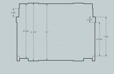
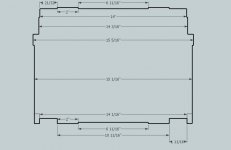
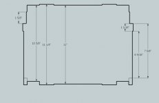
I am indeed in search of 2-D (!) horizontal cross-cut drawing(s) of the inside of the sys-3's, drawings similar to this one from up-thread:

index.php


I understand there could be differences between sys-3 sizes, and if so, I'd appreciate a drawing for each size that has a difference.
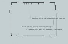
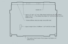
Likewise, the "cross-cut" drawing such as the one I cited may or may not be accurate for the entire depth of a sys-3 (Well I know it's not since there are bulges in the sides at the bottom), so if there is a "depth dependent" cross-cut image for each depth where 'stuff changes', I'd appreciate those too.

If these drawings don't exist yet, but people actually have 3D models (which you seem to imply), then I suppose it would be possible to autogenerate 2D crosscuts from that model, so if someone were capable of doing that, I'd appreciate that - a lot! - as well.

I once did the exercise myself for T-Locs, manually, and what a lot of fun that was  [big grin], so I'm hoping to avoid it this time round.

(If anyone is interested I could find those drawings again I think, in PDF so they could be printed to 1/1 size, and put them up here)
 
First, I don't know why some people (in general) on forums have an issue with bumping / adding to old threads. Makes no sense to me. As far as I'm concerned feel free to use old threads or start new ones as you wish. I'm tired of seeing the "old topic police" ( not necessarily on FOG ) get on peoples case for pulling up old topics. Especially to the point that people feel the need to make apologies for posting on an old thread.

---------------------------------------------------------------------------------------------------------------------------------------
The drawings that I made were done using physical measuring tools ( rulers and such). And "hand" / mouse drawn with whatever very basic drawing program was on my computer at the time. So no CAD files etc. For those using the measurements, I would say they are quite accurate, but may not be perfect.

Seth
 
My understanding was that these interior drawings/models were posted in another thread somewhere here on the FOG already.

It's not just the base dimensions you need to worry about, but all of the undulations, too.  Either the T-LOC and/or Sys3 have a cross-bar shaped riser in the base and the "feet" are lower than the base, making an interior dimensioning "tricky" to say the least.
 
squall_line said:
My understanding was that these interior drawings/models were posted in another thread somewhere here on the FOG already.
Cool, so the drawings already do exist? Now if only someone remembers where…

squall_line said:
It's not just the base dimensions you need to worry about, but all of the undulations, too.  Either the T-LOC and/or Sys3 have a cross-bar shaped riser in the base and the "feet" are lower than the base, making an interior dimensioning "tricky" to say the least.
I probably should have added that I personally don’t need the details on the reinforcement cross(es) in the bottom, as that would be way over the top, and not applicable for me anyway. (Of course maybe other people do want to go that far)

Maybe it helps if I point out why I need these drawings: I want to make custom inserts – from 5mm ply, likely – for some sys3’s (that are on backorder, grmbl, but I digress) but of course I need to be able to lower them in/pull them back out again. So I need the most limiting crosscut drawings for each depth where a bulge would impede vertical access. Since the inserts wont sink into the cross-shaper riser in the bottom – they will in fact rest on it – I personally would like to see the crosscut(s) from just above this cross.

PS: I found the PDFs for II and III T-Locs, included is one that has the measurements (and funny language comments). Like Seth, these were made by swearing a lot by hand with rulers, tape-measures and such, and then drawn up by swearing more in CorelDRAW.
 

Attachments

Back
Top