PeterPorter
Member
- Joined
- Feb 18, 2024
- Messages
- 3
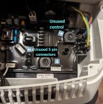
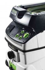
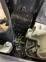
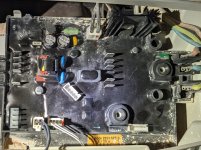
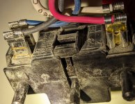
Recently cleaning out a 2016 110v Festool CTL26 I noticed there's two unused 5 pin headers on the PCB and a rotating control that isn't used. Does anyone know what these are actually for? I'm wondering if there's maybe some features that arent implemented on this model but are actually there which I could access via those headers.
View attachment 1
View attachment 1