Drilling MFT Holes

Rusty nuts

Member
Joined
Jan 1, 2012
Messages
23
Hi,
Apart from CNC which I have found to be disappointing is there a sure fire way to do the holes in a purpose built MFT table, I have had one made from 1" MDF and find it unsatisfactory in use so am going to make one myself, the one I have had made is 4'x6' and I find it a good size.
Thanks in advance and apologies if the subject has already been covered.
I find this forum is one of the best ones around for woodworkers and the info gained here is priceless.
Regards
Rustynuts.
 
Rustynuts said:
Hi,
Apart from CNC which I have found to be disappointing is there a sure fire way to do the holes in a purpose built MFT table, I have had one made from 1" MDF and find it unsatisfactory in use so am going to make one myself, the one I have had made is 4'x6' and I find it a good size.
Thanks in advance and apologies if the subject has already been covered.
I find this forum is one of the best ones around for woodworkers and the info gained here is priceless.
Regards
Rustynuts.

I'm curious as to why you found a CNC cut top 'disappointing'? That is without a doubt the best way you're ever going to make one (assuming the guy drawing it up/programming the machine is competent, and gets the hole size & spacing correct!).
 
Holes were not the right size, was turning into a long drawn out saga as to why,how,what,when to get it altered so I am thinking is there another way.
 
Rustynuts said:
Holes were not the right size, was turning into a long drawn out saga as to why,how,what,when to get it altered so I am thinking is there another way.

If the holes are the wrong size then that's a problem with the execution, not the method! A CNC will give you more accurate holes than any other way of doing it.

FWIW, I bought an MFT1080 top & used that as a template to make an oversized top. There's a thread on it here.

You can also do it with the LR32 set-up & a router, if you have that? There are a couple of threads on that somewhere too.
 
jonny round boy said:
Rustynuts said:
Hi,
Apart from CNC which I have found to be disappointing is there a sure fire way to do the holes in a purpose built MFT table, I have had one made from 1" MDF and find it unsatisfactory in use so am going to make one myself, the one I have had made is 4'x6' and I find it a good size.
Thanks in advance and apologies if the subject has already been covered.
I find this forum is one of the best ones around for woodworkers and the info gained here is priceless.
Regards
Rustynuts.
I'm curious as to why you found a CNC cut top 'disappointing'? That is without a doubt the best way you're ever going to make one (assuming the guy drawing it up/programming the machine is competent, and gets the hole size & spacing correct!).

The machine operator (which may not be the programmer) has total control and responsibility for the final hole size through the machine's cutter compensation.  [smile]
 
RonWen said:
The machine operator (which may not be the programmer) has total control and responsibility for the final hole size through the machine's cutter compensation.   [smile]

Very true, but if the programmer calls for 20.00mm holes, when they should be 19.90mm, then they're still going to be wrong!

I tend to assume that the guy programming it & the guy running it are one & the same, since that's what I did on the CNC I ran. [embarassed]
 
The point is that if ordering a top from a CNC shop, specify the precise hole size required depending on the dogs being used & that is what you should receive.

Keep in mind a good shop won't simply drill the holes & depend on the drill size to get the correct hole dimension -- they will drill an under size hole and then go back into the hole with a milling type cutter and with circular interpolation finish the hole to the exact size specified.
 
If you are going to go ahead and do it yourself, Peter Parfitt did this as part of a work bench video. and I believe there is a section/excerpt to the making of his own MFT section.

 
I have a few customers locally that made oversize tops using the LR 32 system and the Festool 20mm boring router bit. Two of them borrowed my LR 32 set and the others now own a set. It works well.

The 96mm spacing is easy - just use every 3rd index. There are different ways to do the layout.

Tom
 
The Festool bit is a boring bit. The one I see at your link is a straight bit.

Tom
 
Tom, Thanks. I think the Wealden one is suitable for boring as it has cutters on the underside as well as sides.
 
You're right, Cliff. A straight bit can be used for boring but it isn't optimized for the task. They normally just have a straight cutter on the face and straight cutters on the sides. They are really designed for moving laterally.

A boring bit is designed for plunging into the work. The first thing that touched the work is a centering cutter. In the case of the 20mm Festool bit, it is a point in the middle of the bit. The next part of the bit to touch the work is cutters that protrude along the perimeter and score the circumference of the hole it's making. Finally, the material removal part, which is equivalent to the straight cutter on the face of a straight bit, sees the work. It is also optimized to make a neat hole.

[attachimg=#1]

'Sorry about the quality of the image but I hope it shows what I mean.

Tom
 

Attachments

  • BoringBit.jpg
    BoringBit.jpg
    238.9 KB · Views: 2,087
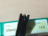
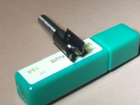
I have the 20mm Festool boring bit, but I also have the 13mm equivalent of the 20mm Wealden bit that Cliff mentions.

The Festool bit is definitely "optimised" for boring holes. As Tom mentioned, it has several characteristics that make it perfect for that job. It's certainly the tool I'd use for drilling 20mm holes á la MFT/3.

[attachimg=#]

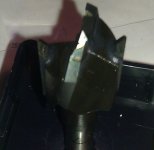
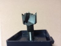
However, the Wealden bit is also optimised for plunge cutting. As the linked page notes, "sizes above 9mm diameter have an additional centre carbide tip to ensure a faster and cleaner cut when plunging". I've taken a couple of photos that hopefully show the cutter in a better light than the outline drawing on the web page. Hope this helps.

[attachimg=#]

[attachimg=#]
 

Attachments

  • photo 2 (2) - Copy.JPG
    photo 2 (2) - Copy.JPG
    70.4 KB · Views: 2,374
  • photo 3 (1) - Copy.JPG
    photo 3 (1) - Copy.JPG
    130.3 KB · Views: 2,118
  • photo 4 - Copy.JPG
    photo 4 - Copy.JPG
    173 KB · Views: 2,101
Why bother with expensive special bits?  If you already have a mft top - simply trace the holes with pencil and free hand plunge rough cut them with a 1/2" mortising bit in a plunge router, then clamp the two boards togther and use a 1/2" pattern bit on the same plunge router.  Perfect holes, perfect spacing, no worrying about bits/sizes/dulling, etc.

JT
 
Tom, thanks for such a detailed reply - reading yours and Garry's recommendations for the Festool bits I am leaning towards the Festool one. I actually recently bought the Wealden 25mm cutter which I used for cutting a hole and the results (visually) were superb (it was for a Hafele drawer front adjuster) but I suspect this was not as stringent a test as a hole in an MFT.

Julian's idea is an interesting one - I always thought that pattern bits don't quite cut to the level of the bearing and so I would have thought that the holes would be slightly smaller in diameter - is this not the case? A slight problem with this approach is that I think my MFT top is slightly warped through water ingress (spilled water due to clumsy sharpening)
 
The Wealdon bit shown will certainly plunge but the set up needs to be really secure. If you look at the periphery you can see that it has a lot of clearance for side cutting. A true plunge drilling tool is circular ground which allows it to make its own guide bushing as it drills and also has no clearance to allow it to cut sideways. That said, plunge mills can make very nice bores, at accurate sizes, if the set up allows for no lateral movement and the spindle is stout and true. Plunge mills usually will not clear chips as well, as they are usually used in situations where they plunge and move sideways at the same time or in relatively small alternating increments. If the plunge mill becomes your choice you should retract it more often to clear chips
 
Here is a thought.  The problem is how to get consistent holes in an x y & z axis.   

Standard hole pin jigs usually have a 32mm spacing.  You can use every third hole in the jig to get the 96mm spacing between holes.  By using either a router or a Drill you can modify the template for 20mm hole drilling.  Using a rail,  you can then do x, y and z.  For a drill,  you can use one of those vertical Drill support jigs. 

 
Back
Top