ear3
Member
- Joined
- Jul 24, 2014
- Messages
- 4,341
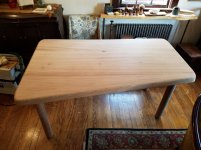
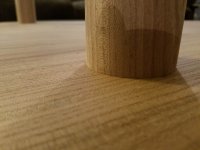
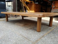
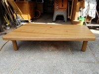
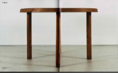
Took a commission a few months back to build an elm kitchen table. The client was inspired by the ultra-modernist design of this French furniture maker, Pierre Chapo, who built most of his stuff in elm, and wanted to riff off of this piece:
View attachment 1
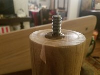
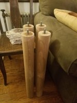
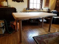
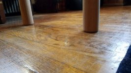
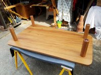
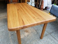
Other than the cylindrical, apron-less legs attached directly into the table top, the key design feature are the splines between the boards on the top. The major modification for our version was the overall shape, which needed to conform to the dining nook they are constructing in their kitchen, and so will be half-trapezoidal: 60" long and then 30" and 39", respectively, on the ends.
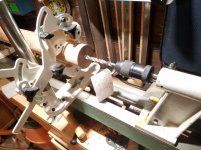
This is not really the sort of piece I would build for myself, but I decided to accept the commission mainly for the opportunity to build with elm, which I had never worked with before. In addition, despite the simplicity of the design (or maybe precisely because of the simplicity), there are few places to hide or disguise any mistakes, and so it was a chance to test my precision in a couple of areas, particularly in regard to lathe work.
The first challenge was sourcing the material. I don't know that much about the history, but from what I understand elm's popularity as a furniture wood took a dive after the native population was devastated by Dutch Elm disease in the 70s and 80s, and so it's not something that most lumber yards stock these days. I called at least a dozen places in the New York area to find out, and the best I could come up with were 4/4 or elm slabs from trees that the New York City Park Service fells in the course of its normal upkeep. So I ended up having to extend the radius of my search, until I finally came upon Berkshire Products in Western Massachusetts:
http://www.berkshireproducts.com/
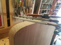
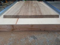
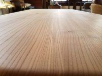
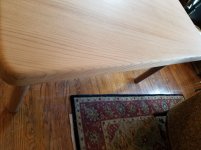
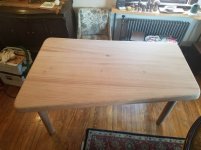
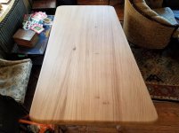
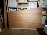
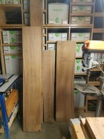
It ended up being about 110 mile drive one way, the last 40 of which were on back county roads, but it was totally worth it, as I came away with a haul of beautiful wide quarter- and rift sawn boards all from the same tree
View attachment 2
View attachment 3
View attachment 4
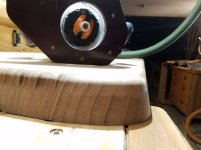
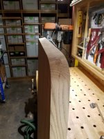
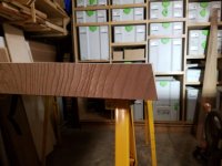
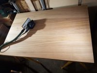
I've heard that elm moves more than other woods, so the fact that they were sawn this way is a good thing from a long-term stability standpoint, even though that meant we wouldn't get any cathedral grain patterning. They were priced at 10/4, but you can see by the tape measure that was generous for me. That left more than enough excess to joint the faces flat with the scrub plane:
View attachment 5
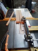
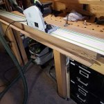
And then rip with the TS75 + panther blade some of the wider, 15" boards down to 12" so they could fit in my planer:
View attachment 6
Planed the boards down to 2 3/16 since the final thickness is going to be 2 1/8".
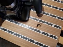
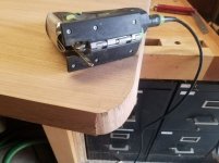
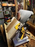
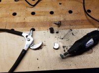
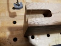
I decided to do the spline as a faux-detail, mortising the last few inches of each end with the Domino XL:
View attachment 7
That's when I discovered that the fence on my XL was slightly skewed, leaving that ripple effect in the mortise. Cleaning that up was actually a nice chance to use the paring chisels I recently got from Blue Spruce, which made it easy to take minute shavings off the mortise walls until they were reasonably flat:
View attachment 8
The greater length of the paring chisels and the flexibility of the thinner steel makes it easier to feel out the flatness you're trying to create.
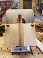
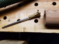
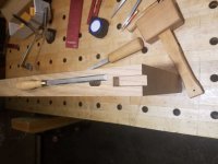
I used the planer to get the approximate size on the spline stock (which was milled from the offcuts of the wider board rips), and then hand fit each one snugly into the mortise:
View attachment 9
View attachment 10
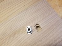
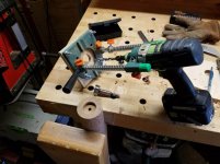
It did a final trim of the boards to width using the TS75 and the 36T blade, which gave a good enough edge for glue up. The width and number of boards was basically dictated by the shape of the top -- to do the angled side, I needed a board 11 1/2" - 12" wide (39" - 30" = 9" plus 2.5-3" extra to handle the radiused corners of the final design such that the spline remains on the end of the table, and is not rounded out to be revealed on the side). So after mirroring this on the opposite side of the table, this meant a top made up four boards at 11 1/2" + 8" + 8" + 11 1/2" The working joinery of the table top was done via 14mm dominoes along the interior edge -- I'm glad I double checked mortise placement prior to glue up though:
View attachment 11
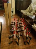
With such heavy boards and dominoes, it was a good thing that I recently got a set of 48" Bessey I-Beam clamps, which deliver a whopping 7000lbs of pressure -- the 2000lbs of the regular parallel clamps would not have cut it I think. Since I only had a single pair of 48" bow clamps, I also manufactured two sets of cauls from some square steel tubes to keep the boards roughly flat under so much pressure:
View attachment 12
View attachment 13
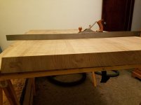
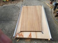
Cleaned up the resulting slab with my rarely used RS2 to keep everything flat:
View attachment 14
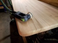
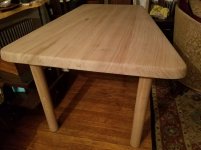
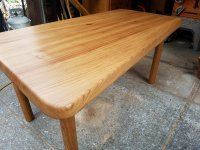
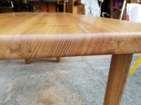
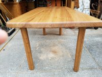
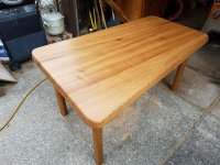
Trimmed the slab with the TS75 to the final dimensions with a 12 degree bevel, which is the angle used in the source image. The splines came out nice and tight:
View attachment 15
View attachment 16
View attachment 17
Next up: turning the legs and problems with the top.
View attachment 1
Other than the cylindrical, apron-less legs attached directly into the table top, the key design feature are the splines between the boards on the top. The major modification for our version was the overall shape, which needed to conform to the dining nook they are constructing in their kitchen, and so will be half-trapezoidal: 60" long and then 30" and 39", respectively, on the ends.
This is not really the sort of piece I would build for myself, but I decided to accept the commission mainly for the opportunity to build with elm, which I had never worked with before. In addition, despite the simplicity of the design (or maybe precisely because of the simplicity), there are few places to hide or disguise any mistakes, and so it was a chance to test my precision in a couple of areas, particularly in regard to lathe work.
The first challenge was sourcing the material. I don't know that much about the history, but from what I understand elm's popularity as a furniture wood took a dive after the native population was devastated by Dutch Elm disease in the 70s and 80s, and so it's not something that most lumber yards stock these days. I called at least a dozen places in the New York area to find out, and the best I could come up with were 4/4 or elm slabs from trees that the New York City Park Service fells in the course of its normal upkeep. So I ended up having to extend the radius of my search, until I finally came upon Berkshire Products in Western Massachusetts:
http://www.berkshireproducts.com/
It ended up being about 110 mile drive one way, the last 40 of which were on back county roads, but it was totally worth it, as I came away with a haul of beautiful wide quarter- and rift sawn boards all from the same tree
View attachment 2
View attachment 3
View attachment 4
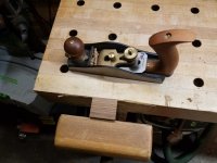
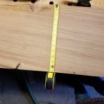
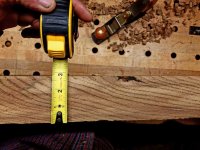
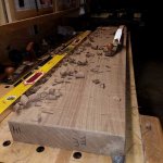
I've heard that elm moves more than other woods, so the fact that they were sawn this way is a good thing from a long-term stability standpoint, even though that meant we wouldn't get any cathedral grain patterning. They were priced at 10/4, but you can see by the tape measure that was generous for me. That left more than enough excess to joint the faces flat with the scrub plane:
View attachment 5
And then rip with the TS75 + panther blade some of the wider, 15" boards down to 12" so they could fit in my planer:
View attachment 6
Planed the boards down to 2 3/16 since the final thickness is going to be 2 1/8".
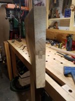
I decided to do the spline as a faux-detail, mortising the last few inches of each end with the Domino XL:
View attachment 7
That's when I discovered that the fence on my XL was slightly skewed, leaving that ripple effect in the mortise. Cleaning that up was actually a nice chance to use the paring chisels I recently got from Blue Spruce, which made it easy to take minute shavings off the mortise walls until they were reasonably flat:
View attachment 8
The greater length of the paring chisels and the flexibility of the thinner steel makes it easier to feel out the flatness you're trying to create.
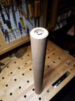
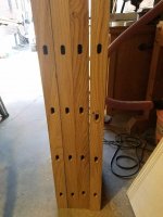
I used the planer to get the approximate size on the spline stock (which was milled from the offcuts of the wider board rips), and then hand fit each one snugly into the mortise:
View attachment 9
View attachment 10
It did a final trim of the boards to width using the TS75 and the 36T blade, which gave a good enough edge for glue up. The width and number of boards was basically dictated by the shape of the top -- to do the angled side, I needed a board 11 1/2" - 12" wide (39" - 30" = 9" plus 2.5-3" extra to handle the radiused corners of the final design such that the spline remains on the end of the table, and is not rounded out to be revealed on the side). So after mirroring this on the opposite side of the table, this meant a top made up four boards at 11 1/2" + 8" + 8" + 11 1/2" The working joinery of the table top was done via 14mm dominoes along the interior edge -- I'm glad I double checked mortise placement prior to glue up though:
View attachment 11
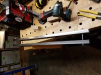
With such heavy boards and dominoes, it was a good thing that I recently got a set of 48" Bessey I-Beam clamps, which deliver a whopping 7000lbs of pressure -- the 2000lbs of the regular parallel clamps would not have cut it I think. Since I only had a single pair of 48" bow clamps, I also manufactured two sets of cauls from some square steel tubes to keep the boards roughly flat under so much pressure:
View attachment 12
View attachment 13
Cleaned up the resulting slab with my rarely used RS2 to keep everything flat:
View attachment 14
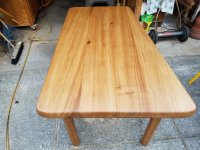
Trimmed the slab with the TS75 to the final dimensions with a 12 degree bevel, which is the angle used in the source image. The splines came out nice and tight:
View attachment 15
View attachment 16
View attachment 17
Next up: turning the legs and problems with the top.
Attachments
-
 Elm Table_Page_1.jpg56 KB · Views: 323
 -
 20190122_191351.jpg489.6 KB · Views: 322
 -
 20190122_190543.jpg495 KB · Views: 250
 -
 20190122_190724.jpg467.7 KB · Views: 264
 -
 20190120_152625.jpg65.4 KB · Views: 237
 -
 20190119_230309.jpg87.9 KB · Views: 275
 -
 20190119_175844.jpg83.4 KB · Views: 189
 -
 20190113_131224.jpg179.8 KB · Views: 208
 -
 20190112_184017.jpg183.9 KB · Views: 228
 -
 20190112_183640.jpg73.9 KB · Views: 173
 -
 20181212_191116.jpg189.1 KB · Views: 272
 -
 20181222_140909.jpg36.6 KB · Views: 227
 -
 20181212_191444.jpg83.4 KB · Views: 246
 -
 20181222_172903.jpg44.3 KB · Views: 221
 -
 20181222_160849.jpg50.2 KB · Views: 225
 -
 20190112_162220.jpg52.3 KB · Views: 244
 -
 20190113_173354.jpg59.2 KB · Views: 194