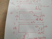
Ever seen a shop drawing this bad?

Crazyraceguy

Member
Joined
Oct 16, 2015
Messages
4,901
Of all things, this was done by a guy with years of experience, at least 10 more than me.
I clearly didn't look at it too well when he first handed it to me this morning, but when I got to it, later in the day, I was shocked. Mostly confused, because I know he looks at our typical drawings every day.
When I went looking for this person to get clarification, he was out somewhere. Another one of the office guys asked if he could help, so I showed it to him. He confirmed what I thought it meant, saying that this guy does this every time. I'm baffled, I understand what it means, but it just looks so wrong.
 

Attachments

  • Drawing fail.jpg
    Drawing fail.jpg
    200.7 KB · Views: 520
Are the arrows facing in the opposite direction of the standardized, customary method of drawing dimension arrows?

On part #1, both of them 3 5/16" from the lower edge of the piece, with one 7 5/8" from the right and the other 13 3/4" from the far right?

At least his handwriting is legible!
 
Looks almost like the arrowless standard except slightly modified to allow him a choice of datum for each feature.
 
squall_line said:
Are the arrows facing in the opposite direction of the standardized, customary method of drawing dimension arrows?

On part #1, both of them 3 5/16" from the lower edge of the piece, with one 7 5/8" from the right and the other 13 3/4" from the far right?

At least his handwriting is legible!

I'd say they're 3 5/16" from the top edge.
 
8)
Nice.  Looks like a standard drawing with measurements from a standard reference location (top left hand corner?)
Piping isometrics are often very similar.  The datum point is the most important location on the drawing.

Regards
Bob
 
Lincoln said:
squall_line said:
Are the arrows facing in the opposite direction of the standardized, customary method of drawing dimension arrows?

On part #1, both of them 3 5/16" from the lower edge of the piece, with one 7 5/8" from the right and the other 13 3/4" from the far right?

At least his handwriting is legible!

I'd say they're 3 5/16" from the top edge.

That's what I thought, but if the arrows (pointing left) are consistent then the other measurements are from the left edge?

Seems like he mixed up his reference pointers. Still, overall more consistent than the drawings I provide myself...

RMW
 
guybo said:
woodbutcherbower said:
Those imperial measurements alone would be unfathomable to me.
a few more pints and you will get it

That's funny.  A pint is an imperial measurement.  To confuse the matter, is that an US pint or British pint-both are different.  The Tower of Babel lives on. 
 
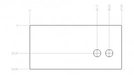
In mechanical industry, Ordinate Dimensioning is very common.
On a complex part, it really decreases the clutter on the drawing.
But I have never seen what you posted.
In the industries I have worked in, parts are dimensioned to ANSI standards and one is not allowed to invent his own drafting standards.
[attachimg=1]
 

Attachments

  • Ordinate 1.jpg
    Ordinate 1.jpg
    26.4 KB · Views: 538
Actually it's a form of ordinate dimensioning shorthand...if he had used traditional ordinate dimensioning like Steve1 shows, he'd not be able to get 3 different panels on a single piece of paper. Pretty clever use of a small dimensioning space and he's still able to produce a readable drawing without shrinking the size of the numbers.

I am confused though with the arrow direction in the lower RH corners, seems like the arrow directions should be rotated 180º.
 
The parts that are the clearest are the overall dimensions and the color of the cork/linoleum covering, which is Potato Skin, by Forbo. :)
 
The bar with arrows is shorthand for which datum edge the measurement is from.  This deviation in standard falls apart in complex geometries.  But we're dealing with drywall/panel sheets here.  The plus side to explicit datum marking is that one can measure from any side (usually closest and most accurate) and just note it directly on the paper without rejittering numbers to correspond to the previously established global datum (standard top-left, but with foresight would have been bottom right in these examples). 

I use a similar system when measuring rooms.  I can draw ANSI marks, but like you said, the bars clutter small drawings and formal ordinate requires onsite math.  Passing technical drawings for archive though would have it redrawn, but we seem to be complaining about a missing TPS cover sheet on a napkin drawing.
 
So there are three separate datums (zero points) being used in drawing number 2 and 3? Is that what I'm understanding?
 
Cheese said:
Actually it's a form of ordinate dimensioning shorthand...if he had used traditional ordinate dimensioning like Steve1 shows, he'd not be able to get 3 different panels on a single piece of paper. Pretty clever use of a small dimensioning space and he's still able to produce a readable drawing without shrinking the size of the numbers.

I am confused though with the arrow direction in the lower RH corners, seems like the arrow directions should be rotated 180º.

Looks that way to me too. If those arrows are pointing to the origin then the X’s representing holes should be on the left side of the drawing…
 
Looks like he has an asterisk making the center location of wall outlets. Right on the very Top of the drawing there is an explanation for the asterisk    * = center of outlet. Maybe ...
 
squall_line said:
So there are three separate datums (zero points) being used in drawing number 2 and 3? Is that what I'm understanding?

Read it as - bar represents edge, arrow is the direction inward towards feature.  So all three drawing holes measurements are from the bottom right.

Someone might ask, then why not just make the datum from there in the first place.  But really, it depends on which edge might be the most critical.  One might not notice a 1/16 error from the left edge, but you may clearly see it from the right.  Or maybe the bottom edge could just be below knee level so not as critical as the eye-level edge in which I'd personally change the feature datum to be top edge for any panels where it may show.
 
Michael Kellough said:
Looks that way to me too. If those arrows are pointing to the origin then the X’s representing holes should be on the left side of the drawing…

If the actual datum line (0-0) is in the upper RH corner of the part, then the lower RH arrows only have to be rotated 180º to make the drawing correct.

However, if the actual datum line (0-0) is in the upper LH corner of the part, then the two holes need to be physically moved to the LH side of the part AND the 13 3/4 & 7 5/8 dimensions need to be swapped around to make the drawing correct.

Added to this confusing drawing is the fact that the "normal" ordinate dimensioning datum line (0-0) is, 90% of the time, in the lower LH side of the part.  [eek]  It is an ANSI drafting standard.
 
Well [member=58857]Crazyraceguy[/member] , what is the correct translation?  Inquiring minds are waiting  [big grin].

Peter
 
Back
Top