How to remove heat from LED’s trapped inside a frame

Joined
Jan 23, 2007
Messages
7,100
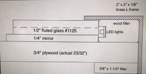
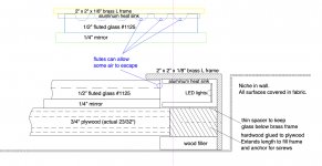
I’m working on a large mirror project that has a continuous strip of bright led’s (about 1 watt per foot) around the perimeter. This framed mirror will be installed in a niche and there won’t be a non-destructive way to remove it to replace led’s if they fail so I’m looking for the best, or a very good way to conduct the heat away from the led’s to prevent failure.

With consultation from Cheese via pm’s I’ve come to the realization that the wood channel housing the led strip needs to be replaced with some configuration of aluminum channel.

I also think the led strip should be positioned deeper (farther away from the fluted glass) so maybe I just need a simple C channel tucked into the corner of the brass frame.

[attachimg=1]
 

Attachments

  • IMG_5178.jpeg
    IMG_5178.jpeg
    1.5 MB · Views: 429
I'm assuming the brass goes on all four sides, I would recess the leds deeper away, from the glass.  If possible, I would have holes in the frames and spacers at the bottom and top in line with the led strips to allow some heat movement.
 
Some idea of how the unit is to be installed would be helpful.

I am a bit concerned that there is not a non-destructive way to remove the unit once installed. In reality even under the beast circumstances there is still some chance of failure. Heat usually takes out in most cases.

Ron
 
Michael Kellough said:
With consultation from Cheese via pm’s I’ve come to the realization that the wood channel housing the led strip needs to be replaced with some configuration of aluminum channel.

Wood is somewhat of an insulator so the "Wood Filler" piece will trap heat. Metals will conduct heat and you're lucky to already have a design with a brass outer frame.

• Yes, mount the LEDs in an aluminum channel. Are they COB or individual? If individual, you might have to add a diffuser to not see individual lights.

• I'd drill holes in the Wood Filler piece such that the aluminum channel covers them that heat can get out that way.

• I'd mill down the Wood Filler piece to be as small and open as possible, just enough to support the aluminum channel. If you really wanted, make as much of the Filler piece from aluminum as you can. That will essentially provide a heat sink. Failing that, better to have open air than wood.

 
Michael Kellough said:
This framed mirror will be installed in a niche and there won’t be a non-destructive way to remove it to replace led’s if they fail …

If it were me, I would spend some brain power to solve this constraint so that you are able to address the inevitable without completely destroying the project.

With that said, how long will these LEDs be powered on each day?
What will be the total length, and thus the total wattage of the LEDs?

With that number you can do some more direct focus on how to dissipate that amount of power and see what mass of aluminum and possibly what amount of airflow will be needed.
 
I agree with jonnyr
Why would one think that they had so much LUCK that they could buy LED components of such high quality?
Murphy wrote his “law” based on ….
 
Michael Kellough said:
[attachimg=1]

Instead of the wood filler at the face, I would use either an aluminum tubing or an aluminum L-extrusion which will make a hollow channel for air to flow.  You can add air flow by installing a 3 watt electronics cooling fan.  They draw very little current and are extremely quiet.  Have it cycle on when the mirror light is on.

I am with all the others that suggested to design around the service issue.

My dad had a 1972 Olds Toronado.  The front signal bulb burned out.  To replace it the dealer wanted $350.00, that’s over $2,100 dollars in today’s dollars). The entire front bumper assembly had to be removed to replace the bulb.

(My memory is not 100% sure on that dollar amount.  It was enough to make my father blanch, but it might not have been $350.00.  The number sounds right, but the $2,100.00 in today’s dollars does not.)

Luckily, my dad’s mechanic had a very tall, very skinny high school basketball player working for him part time.  The kid was able to reach his long, skinny arm in and replace the bulb in just a couple of minutes.

My suggestion is “Don’t be designing a 1972 Olds Toronado”.

toro1-jpg.156251


Thanks for the very helpful comments and suggestions guys!

Right now I’m leaning towards Valent X (24 volt) led strips from Diode LED. They use about 1 watt per foot and this will require about 32 feet. The driver they sell for the Valent X comes in 30 watt and 60 watt (and beyond) so I’d get the 60 watt version.

They also sell a various aluminum channels but the metal shop making the brass frame will also have options.

Background,

The 8 foot wide, 4 foot high mirror/frame will be installed in an arch topped niche in a residence. The home owner wants no more than 1/4” clearance all around the frame so it can’t be hung from Z-clips or the like. Can’t get it high enough within the niche to clear the top of the hanger. So it will have to be screwed directly to the wall.

In order to do that some of the fluted glass elements will be left out to allow access to holes in the mirror where screws will go. When the mirror/frame is shimmed into the proper position the screws will be driven home and the fluted glass elements will be glued in. To remove the mirror the fluted glass pieces would have to be pried out to get access to the screws. Likely a death sentence for the mirror. Then revise the design.

My client owns a venerable company in Manhattan that specializes in decorative cast glass moldings for high end interiors. He hired me to do the graphic design for this project and provide a template for the glass guys to cut the fluted glass. He left the led stuff to the metal working shop. I worked from dimensions provided by the interior designer (based in Massachusetts) but they didn’t make sense. So we had the client provide a paper template of the opening which brought up even more questions no one could answer so I have to fly to LA next week and measure it myself.

I was going to use a digital range finder but I don’t think it will work (see paragraph below) so I’ve made an expanding story stick using the fittings Lee Valley sells and for the ~108” diagonals I’ve got “light duty telescoping aluminum framing and fittings” from McMaster. (I prefer the lever lock fitting to the wing screw type)

I knew about the led lights early on but at that time the frame was to be 1/2” smaller all around than the opening so it could be removed if needed. Then they changed the spec to 1/4” and sent a photo of the niche which revealed that the entire area is now upholstered in a velour type fabric [scared] and shows an electrical junction box dead center in the niche. Behind the mirror that will be immovable.  [eek] I don’t know the California electrical code but I’m pretty sure that isn’t allowed.

So I asked my client about the led system and he asked the metal guy and it turns out the metal guy was just going to use some cheap stuff from Amazon, in a groove in wood. What little I know about LED’s comes from Cheese’s excellent posts on the subject here but it is enough to suspect that the current scheme is a recipe for failure. Now that I’ve got a lot more skin in the game I feel like it’s on me to come up with a satisfactory design for the LED’s and then tell the metal guy what to get. And get the electrician on the Joe to find a good (serviceable) place for the driver.
 
Michael if you're the project leader...you just became the project manager.  [smile] That's always been the handoff.

This additional information is interesting and really buttresses the advice I gave earlier...semiconductor failure is 90% of the time heat dependent and LEDs are semiconductors.

Knowing that the mirror is 4' x 8' is important information. You have 24' of LEDs that are potential time bombs. LED systems that are compromised can manifest themselves in several ways, all the LED's refuse to light, some of the LED's refuse to light, the LED's start to flicker, the LED's start to dim but then come back to their normal intensity...or all of the above at the same time...it can become a hot mess.

Per our previous discussions, at some time all LED's will fail, and the only way around that is to provide for some manner of future replacement. I'd suggest that the "fluted glass elements" that cover the installation screws, be marked in some nondescript manner and rather than being permanently installed, be installed for easy removal instead...magnets come to mind.  That way the mirror lighting can be serviced when the inevitable happens.

Looking at that wood filler, it appears to be approximately 3/4" wide x 1-3/8" deep. I'd suggest that you replace that with some 3/4" x 1-1/2" aluminum tubing with 1/8" wall thickness. You can trim that extrusion to whatever final dimension you need. With that amount of aluminum tubing acting as a heat sink, you'll probably not need to conductively attach the aluminum to the brass frame.

That larger aluminum profile will provide 9x more heat capacity than the typically sized aluminum profile used for that application.
 
I suggested aluminum tubing too, but primarily as a way to move air using a small electronics cooling fan. 

It seems you feel that the passive heat sink will be adequate.  And I am now thinking about the corners.  How to join the tubing at the corners to allow airflow around the entire perimeter. 

With passive cooling there is no fan to fail, but it seems like you need to be an engineer to figure the right amount of ribs for the cooling and where the heat will go once it leaves the heat sink. 

I built a “cat cabinet” once, that held the cats’ litter boxes.  I used one of those fans to create a negative atmosphere and vent outdoors. With the fan on, no odors escaped the cabinet, despite a rather larg 6” x 9” access opening for the cats.

Very low CFM fan, very quiet, very low electric draw, and under $10.00.  So I would consider the fan in addition to the heat sink if you have a place to vent the heat to.
 
Packard said:
1. I suggested aluminum tubing too, but primarily as a way to move air using a small electronics cooling fan. 

2. It seems you feel that the passive heat sink will be adequate.  And I am now thinking about the corners.  How to join the tubing at the corners to allow airflow around the entire perimeter. 

3. With passive cooling there is no fan to fail, but it seems like you need to be an engineer to figure the right amount of ribs for the cooling and where the heat will go once it leaves the heat sink. 

4. Very low CFM fan, very quiet, very low electric draw, and under $10.00.  So I would consider the fan in addition to the heat sink if you have a place to vent the heat to.

1. Packard, I liked your suggestion of installing a muffin fan for air circulation. I didn't proceed in that direction for 2 reasons. The 1st is the watt density of the LEDs that Michael has specified will deliver a relatively small thermal load that needs to be managed. The 2nd reason is as you've already addressed, air flow around the square corners of the aluminum profile will probably be an issue.

2. I do think a passive system will be adequate because of the low wattage rating. As an aside, I installed Diode LED Ultra Blaze LEDs under the kitchen cabinets for task lighting. Those are rated at 4.3 W/ft while Michael is using Valent LEDs rated at 1 W/ft.

Also, in many of the LED projects I've done I've been able to minimize the thermal load by being heavy handed and simply adding more aluminum to the system...[smile]...kind of like the Tulikivi effect.  [big grin]

3. Not having another electrical component to worry about is always a good thing.

4. Again, I've used muffin fans to cool high power audio amplifiers in the past and I like them a lot because of the thermal load they can quietly manage. I've also noticed that the new fans are several magnitudes quieter than the original "Muffin" fans.

When I was looking at your fan suggestion originally, I figured 2 fans may be necessary to deal with those pesky square corners. Just like a long, heavy train...you need a pusher & a puller.  [smile]
 
A fan would be nice as long as it was supplemental and silent and its failure would not be disastrous. Also, it would have to very tiny and there is nowhere for air to escape, it would just circulate within the aluminum channel. And as Cheese pointed out air doesn’t do much thermally compared to aluminum. (Oh, and Cheese, thanks for pointing out that the frame only uses 24 feet of LED’s not the 32’ I wrote earlier.)

Based on the good advice given here I’m leaning towards the aluminum 1-1/2” x 3/4” x 1/8” leg C channel attached to the brass frame with thermally conducting tape and setting the led strip all the way in to the bottom of the channel. The led strip is just under 1/2” wide. The front face of the brass frame will be out in free air so it will radiate some of the heat away. Also, I think the 120* light beam angle needs to be reduced

The Diode Led spec sheet says the temperature of the leds needs to be kept below 122*f (50*C). Does anyone know about thermocouples or other ways to cut power when it gets too hot?

However, now I’m not sure what the wattage per foot will be. The lowest is the 100 lumen/foot 1 watt/foot strip but if that means the LED’s are widely spaced then we’ll probably have to use the higher wattage strips. To be determined. The studio will have to make a mockup and I’ll also ask them to figure out a nondestructive way to remove the glued on (or however) fluted glass pieces that cover the screws.

I’ll post better drawings if able.
 
Michael is the mirror unit proud of the wall when installed and and the side of the brass angle exposed or is just the face of the brass visible?

Based on you first drawing it appears that the mirror itself is installed on a plywood base that is 1 3/4 larger on all 4 sides.

How about fabricating the piece so the plywood and mirror get mounted to the wall with fasteners and then the brass/aluminum led unit is mounted separately somehow. That would allow that unit to be removed to replace the led strips if needed.

Ron

 
They sell mirrors with lights built in.  I would be inclined to buy a small one just to see how they handled the issue. 

I did google “low heat LED light strips” which Google’s AI changed to “Low temperature” which seemed to mean 2700 Kelvin, and referred to the color temperature and not the actual temperature.

I do seem to recall a ad for LED strips that generated less heat than others, but Google thwarted my efforts to find it.

Actually the tubing mitered in the corner and using L-brackets like the aluminum picture frames use would not impede air flow. 

So that issue is conquerable.

But even if you conquer the heat issue, some one in the distant future will be cursing the designer who put in lights that could not be replaced. 

It seems to me that I saw a magnetic solution to this sort of problem.  The magnet moved the latch that anchored the panel.  I have no idea where I saw it though.

product-image-1444.jpg


Alternatively, you could have interlocking extrusions at the bottom of the unit and several  magnetic latches at the top.  The magnet does not hold the glass in place.  The magnet releases the latch.  This not the one I saw in the past, but several might work.
https://www.alzstore.com/invisible-...rce=google&gad_source=1&utm_campaign=Campaign+-+PLA+Shopping&utm_medium=pla&gbraid=0AAAAADQE7o61zFentdBdq-_W-Ps2eV7P8

Lee Valley sells one, but the low price makes me believe that it is not heavy duty.

Perhaps you can run a piano hinge on one side and latch the other
https://www.leevalley.com/en-us/sho...GAoP46BKLdL8kzhp2DyN09yoeL6UQf3-1Lw6SBJOugl8g
 
The maximum temperature they quoted is a concern, but I would be as concerned about lower but still "elevated" temperatures that lead to premature failure.  Figuring out how to make the piece serviceable seems pretty important.
 
Furnace high limit switch is the kind of thing I was hoping for but I didn't know existed. I wonder if there are lower temp versions? It could be attached to the aluminum channel with conducting tape and whatever else is needed to keep it tight.

Packard, the magnet release is also interesting. This thing will weigh about 400 pounds and it will be in private house (mansion really) in Santa Barbara so I think the way it's fastened to the wall needs to be more secure. However, it now occurs to me that if a large area of the plywood panel is cut out a low angle French cleat (the pitch would be limited to 3/16" over 3/4") could support the weight and half as many screws would be needed to keep it on the wall.

[attachimg=2]
 

Attachments

  • Solana Corner detail aluminum flutes.jpg
    Solana Corner detail aluminum flutes.jpg
    500.7 KB · Views: 15
  • Solana Corner detail aluminum flutes.jpg
    Solana Corner detail aluminum flutes.jpg
    500.7 KB · Views: 246
I like the new drawing Michael, especially the hot air venting through the flutes.  [big grin]

Some sort of prototype of a frame/glass section will have to be done to find the final position of the LEDs. You want maximum light levels but with the least amount of wattage and thus the least amount of heat to control. If the LEDs were to remain in their original position close to the glass, they'd provide single point light sources around the entire frame which can be unnerving to most folks. To obtain a softer quality of light, the LEDs need to have a frosted/diffusion lens placed in front of them or they need to be moved further from the edge which then increases the wattage needed. A short prototype section of the frame should easily solve this issue.

The location of the driver needs to be considered for potential servicing. If you can stick with the 1 watt LEDs, then a small 30 watt driver, which can be easily hidden, will suffice.

The HVAC thermostat that was mentioned is usually called a snap-action thermostat. Honeywell and White-Rodgers manufacture them for the HVAC industry. Lots of options and easy to mount.

More good news... [big grin] ...the brass frame is generally a good thermal conductive material. The conductivity value is about half that of aluminum but twice that of steel.

The 122ºF temp that Tech Service gave you is just a generalization...but still a valid one. What they're really concerned with is the LED junction temp but that point is buried inside the LED and is just about impossible to measure directly. The junction temp should be maintained in the 85º-90ºC range (185º-194ºF).  This example is just to give you an idea of the permissible temp range you can operate in. The max heat sink temp you want to see is probably 150ºF, at least that's what I usually shoot for. When I run a new product continuously for 5-6 days, if the heat sink temp has plateaued at/below 150ºF, that's good enough and the actual installation longevity usually bears that out.
 
I feel better about this design, fueled by suggestions from you guys.

Sent email to Diode Led asking for suggestions for the snap-action thermostats.
I think adding one would be better than trying to pre-manage the clients usage.
Just tell them "if the lights go out wait for them to come back on, then use the dimmer to lower the brightness".
 
I want to get a jump on testing this plan so I ordered a longer strip of the Cob LED’s that smorgasbord bought and this Mean Well 350 watt transformer.

For testing the heat build up this should be enough, other than wires/connectors but I’m clueless when it comes to dimmers. Do I get something that is installed between the 24 volt supply and the LED’s or something that limits voltage to the power supply? See how clueless I am?  [embarassed]

I suppose the client would prefer a dimmer mounted in an ordinary switch box on the wall. Is that possible?
 
Back
Top