This is great, I'm starting to understand all the bits involved. The hall effect sensor is intriguing, but my googling is turning up stuff that doesn't look like it's packaged for plug and play use. Ideally I would want to buy a kit with the switch, relay, driver and LED's all together and ready to wire into the cabinet.
So here is a question. I don't know enough about the wiring yet to understand if this is right. I'm designing a cabinet for my wife (she would say it's going nowhere, but she doesn't appreciate that thinking is half the work!

) which will be waist high about 600mm/24" wide, with two symmetrical doors and a drawer (above or below the doors). So I need:
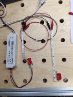
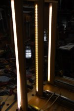
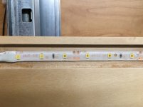
- 2 20" sections of the LED tape
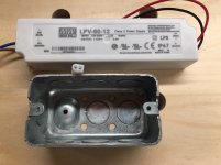
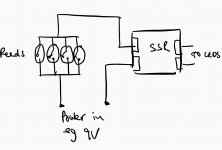
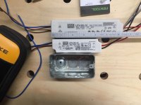
- 1 driver (how much output?)
- 2 hall effect switches
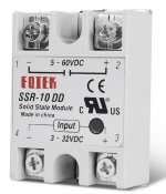
- 1 relay?
There will be two LED strips inside the cabinet, and if either door is opened, I want both LED strips to light. I think that means both switches need to be connected to the driver and relay so either switch can turn the lights on. Does that sound doable?
*Edit*
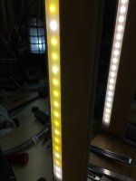
One more thing...I know I want a warm light (2700K tops), but I'm not sure about the intensity. In case the two strips end up being too bright, I may need to dim them, but really only once to get it where I want. Do the drivers come with an integrated dimmer where I could make the adjustment before hiding the driver away in a recessed compartment hidden in the cabinet?