smorgasbord
Member
- Joined
- Jan 7, 2022
- Messages
- 1,154
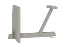
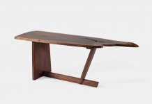
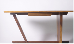
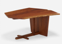
My current design for my slab-top desk's base is this:
[attachimg=1]
The two bottom joints could be half-laps or bridle joints.
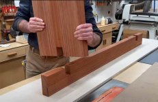
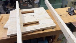
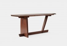
In a recent video, Jon Peters decided to use half laps, just to keep it simple:=2xMoWQ-7U9_LDSR5
Looks like this:
[attachimg=2]
One of his tricks is to cut the joint so that it's a tad too tight, so when he finish-sands the joint will be good.
I'm thinking a bridle joint is stronger:
1) Adds structural integrity.
2) Eliminates the sanding of one of the pieces having an effect on joint tightness.
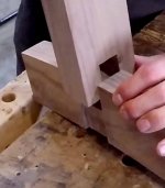
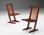
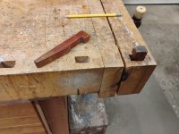
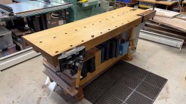
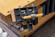
Here's an example of a bridle joint:
[attachimg=3]
From:=zlMoI3uOW46Rev3E
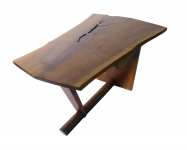
These two bridle joints are pretty much all that will stop my desk from racking, as the connection of the top of the legs to the bottom of the top won't be reinforced with a top stretcher (others have incorporated a top stretcher). I could do that, too, but I think I'd rather just use DF700 connectors so the desk can come apart for moving.
Now, these bridle joints are inherently strong. Nakashima used them for his Conoid chairs to attach the feet to the legs (of which there are only two, so there's a lot of racking forces on them). I think he did something similar for attaching the seat to the two legs, which has even more torque on that joint.
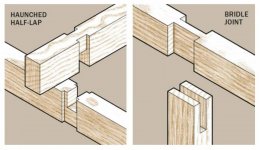
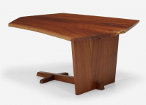
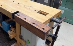
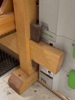
Another thing I could do is "house" or "haunce" the bridle joint. Instead of notching the bottom stretcher for the full width of the vertical leg, I'd notch it narrower. That way the leg could be sanded without affecting the joint tightness/appearance.
[attachimg=4]
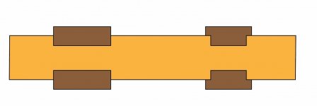
Here's a cross-section of the bridle joint on the left and the housed bridle joint on the right:
[attachimg=5]
For the regular bridle joint, on the left, I can sand the bottom stretcher (yellow) without affecting the joint tightness or appearance. For the housed bridle joint, on the right, I can sand the vertical legs (brown) without affecting the joint tightness or appearance.
I'm pretty sold on the bridle joint over the half lap, even over the housed/haunched half-lap, but am willing to entertain opinions and theories otherwise. But, if I stick with a bridle joint, does it matter if I house/haunch it or not?
For the housed bridle joint I could sand the vertical leg (dark brown) as much as I wanted without affecting the tightness of the joint, as long as I didn't sand in the joint areas, which is pretty simple to do. For the
[attachimg=1]
The two bottom joints could be half-laps or bridle joints.
In a recent video, Jon Peters decided to use half laps, just to keep it simple:=2xMoWQ-7U9_LDSR5
Looks like this:
[attachimg=2]
One of his tricks is to cut the joint so that it's a tad too tight, so when he finish-sands the joint will be good.
I'm thinking a bridle joint is stronger:
1) Adds structural integrity.
2) Eliminates the sanding of one of the pieces having an effect on joint tightness.
Here's an example of a bridle joint:
[attachimg=3]
From:=zlMoI3uOW46Rev3E
These two bridle joints are pretty much all that will stop my desk from racking, as the connection of the top of the legs to the bottom of the top won't be reinforced with a top stretcher (others have incorporated a top stretcher). I could do that, too, but I think I'd rather just use DF700 connectors so the desk can come apart for moving.
Now, these bridle joints are inherently strong. Nakashima used them for his Conoid chairs to attach the feet to the legs (of which there are only two, so there's a lot of racking forces on them). I think he did something similar for attaching the seat to the two legs, which has even more torque on that joint.
Another thing I could do is "house" or "haunce" the bridle joint. Instead of notching the bottom stretcher for the full width of the vertical leg, I'd notch it narrower. That way the leg could be sanded without affecting the joint tightness/appearance.
[attachimg=4]
Here's a cross-section of the bridle joint on the left and the housed bridle joint on the right:
[attachimg=5]
For the regular bridle joint, on the left, I can sand the bottom stretcher (yellow) without affecting the joint tightness or appearance. For the housed bridle joint, on the right, I can sand the vertical legs (brown) without affecting the joint tightness or appearance.
I'm pretty sold on the bridle joint over the half lap, even over the housed/haunched half-lap, but am willing to entertain opinions and theories otherwise. But, if I stick with a bridle joint, does it matter if I house/haunch it or not?
For the housed bridle joint I could sand the vertical leg (dark brown) as much as I wanted without affecting the tightness of the joint, as long as I didn't sand in the joint areas, which is pretty simple to do. For the