Absolutely not a pest. I'm flattered that you want to know more =)
After all, I hadn't been able to build this at all if it weren't for all the inspiration and ideas here at FOG. I'm glad to be able to share back to the forum.
About the boards you're wondering about.
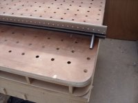
- All interior faces are drilled with 6 x 32mm hole rows. My heavy duty sliders have 6 fastening points, hence the 6 rows.
- The middle board is a sandwiched 19+6+19 mm MDF. Target width was 45 mm to be able to mount sliders on booth sides.
- Side boards are sandwiched 19 mm MDF + 6 mm birch ply. The mdf is on the inside and flush with the 45x45 extrusion
- All boards are routed to fit the 10mm tracks in the 45x45 extrusions.
- The top of the middle board also acts as support for the sub table top (12mm birch ply)
- The middle board is not centered. This way I can store 2x SysMax in one of the wider drawers.
This image shows the MDF sandwich:
[attachthumb=#]
After all, I hadn't been able to build this at all if it weren't for all the inspiration and ideas here at FOG. I'm glad to be able to share back to the forum.
About the boards you're wondering about.
- All interior faces are drilled with 6 x 32mm hole rows. My heavy duty sliders have 6 fastening points, hence the 6 rows.
- The middle board is a sandwiched 19+6+19 mm MDF. Target width was 45 mm to be able to mount sliders on booth sides.
- Side boards are sandwiched 19 mm MDF + 6 mm birch ply. The mdf is on the inside and flush with the 45x45 extrusion
- All boards are routed to fit the 10mm tracks in the 45x45 extrusions.
- The top of the middle board also acts as support for the sub table top (12mm birch ply)
- The middle board is not centered. This way I can store 2x SysMax in one of the wider drawers.
This image shows the MDF sandwich:
[attachthumb=#]