MFT/3 replacement top as a ‘template’ (20mm bushing size?)

Cut Once

Member
Joined
Jan 4, 2020
Messages
6
Hello all,

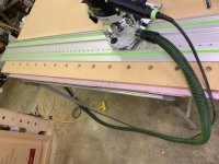
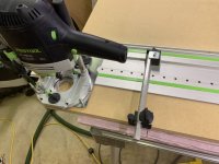
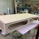
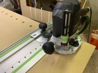
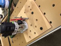
I want to use an MFT/3 replacement top as a ‘template’ to make a larger top, I have seen other people successfully clamp it to the workpiece and then drill out the bulk of the holes with a drill bit. First using a drill bushing to prevent from damaging the top. Then with a router and a flush trim bit to enlarge the hole to match the template. After that they extend the template to a new area by using longer dogs to pin it to the holes already made in the workpiece. Using this method I have seen others make larger 4’ x 8’ size tops.

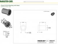
Before I go and spend my money on the wrong tools Does anybody know or have a link to the correct bushing size and drill bit that fits the 20mm MFT/3 holes used to prevent damaging the the top before drilling out the bulk of the holes?  I am hoping that a forum member is familiar with this process and may know exactly what I am looking to do.
 
I used a scrap of some plastic tube. No need to fit well or be concentric. Anything that goes into 20 mm hole and fits your drill bit inside will do. It's just a cushion between the bit and template edge.
1/2" is probably most appropriate flush trim bit for the job, so size your drill bit accordingly - at least 1/2".
 
there are many different approaches - if you are not going to buy an original FESTOOL replacement top and you want really accurate hole pattern here are three alternatives:

1.)download the free CAD files and drawing from TSO's website
https://tsoproducts.com/plans-drawings/worktop-cnc-routing-files/

and take it to your neighborhood commercial Sign company to have them CNC router out several pieces from a 4x8 ft sheet of 3/4" MDF

2.) buy a piece of 3/4" MDF large enough to cut one or more MFT work tops and use a Parf Guide System Mark 11
https://tsoproducts.com/accessories/ujk-technology-parf-guide-system-mark-ii/

along with the free download drawing from TSO's website to make your own tops and other fixtures too.
The Parf Guide System includes the correct boring bit and also has a Parf Dust Port available to effectively remove the MDF chips and dust to prevent interference with the precision hole boring.

If all you want is a hole pattern for clamping and not for accurate layout, you can use any number of inexpensive jigs or the old MFT top itself.

3.) If you just want a suitable boring bit, TSO sells the Parf Guide Boring Bit by itself as a spare part:https://tsoproducts.com/workholding...trotec-drill-bit-spare-for-parf-guide-system/
This bit requires is designed for use with a pre-drilled 3mm pilot hole.

Hans

 
Parf Guide is the ticket! You’ll have what you need to make tops, jigs, quick and most importantly...accurately...in material of your choice.
 
If you are desiring the table to be used as a cutting guide using dogs from any sources I will offer this:  Festool has never spoken about this usage to the best of my knowledge.  Their displayed usage for eons has been for clamping and supporting.  Although their tops are obviously manufactured to a tight tolerance using CNC and work well for tons of us, if using as a pattern your can only create what the pattern will allow.  I guess that can also be said for various jigs and aids, but those were created for a purpose that the Festool MFT's were not.

Offered respectively.

Peter
 
Peter Halle said:
Although their tops are obviously manufactured to a tight tolerance using CNC and work well for tons of us, if using as a pattern your can only create what the pattern will allow.
Agreed. Perhaps it's worth checking whether the pattern top is satisfactory before proceeding with copying it into a larger one.
 
You can also use the LR 32 system if you have one.

Every 3 rail holes would give you 96 mm.

Which I think is what the MFT hole pattern is set at.
 
Using a MFT top as a template works quite while and allows you to make any size of MFT style top that you want - like a 4' x 8'

20mm is .787" so a drill bushing with an outside diameter of 3/4" will fit with a little room to play.  Then pick an inside diameter that is most convenient for you.  (I use 5/8")

McMaster Carr sells the one I use, about $16 plus shippinghttps://www.mcmaster.com/8492a327

Keep in mind that when using a 'pattern' router bit (the bearing is at the top, closest to the router) some manufacturers slightly undersize the cutter diameter compared to the bearing diameter so that the 'pattern' does not cut each time.  As a result, the finished 20mm hole maybe a little tight - which may or may not be a good thing.  If you find this is the case, check the diameters.  I actually called Whiteside (great customer service by the way) and one of their people went out into the shop and found me a bit that the cutter diameter matched exactly the bearing diameter.  For example, I think the Freud bits are a little undersized

View attachment 1


Attachments

  • bushing.jpg
    bushing.jpg
    97 KB · Views: 350
I have built several replacement and oversized MFT tops from an existing MFT top.  It's tedious, but works well.  I built my own drilling jig.  I think I drilled a 9/16" hole so I could get a 1/2" bearing guided bit in there to finish the outside.  Mine was 3 holes in a scrap of MDF that was part of a quick test I had done.  I made the outer 2 holes 20mm and the center hole 9/16.  Then I could just move it from place to place and quickly drill through.  Just take a strip and carefully center drill the 3 holes through the template.  Pattern bit rout the outer two, use a couple dogs and you're good to go.  After a few different tops, I had nicked a couple of the holes in the template top and I had to deal with that during the last build.
 
I agree, it works quite well

When I use the router after drilling the holes, I make sure I use a fixed base - hand position is usually closer to the workpiece so less chance of 'rocking' the bit.  I also use a $20 foot switch and only move the router when it is off.  So with the router off, I place the bit in the drilled out hole, hit the foot switch make a couple of circles and then turn off the router and wait for it to stop to move it.

If I knicked the template hole, I think I would just use some Bondo (auto body filler) to fill it the knick and clean things up
 
As has been said, if you want to copy a Festool MFT top check to be sure it’s really what you want to duplicate.

I have the older style MFT’s, one 1080 and two 800’s, and a spare 800 top.
The hole diameters are different on all 4 tops. Maybe they’re more consistent these days?

Yesterday I setting up the spare top to use on a Dewalt miter saw stand and discovered that some Delrin dogs (I bought at some point) fit the holes nicely so I got got out my best big machinist square and checked the pattern. Using the long side as the base the row perpendicular to that (I only checked one row) was off about .01”. So, the dogs went back into the carton. I’ll get better results using the TSO rail square.

That said, I’ll admit I’m not a fan of the practice of using dogs to set the work and rail. I like the idea but it’s never turned out to be an improvement in accuracy or efficiency, for me. I like the MFT as designed, using the  hardware supplied, and get great results.
 
I’ve mentioned this before, if you use the MFT for clamping & positioning you’re golden, that’s what it was designed to do.  If you think you’re going to use the MFT with dogs for PRECISION squaring/cutting...good luck.

Woodpeckers took 2 new Festool MFTs and an old Festool MFT and measured all three of them on their vision system. All 3 MFTs varied in dog hole diameters and in placement and location of the holes. The person that did the measuring said “I was surprised there was that much variance”.

Remember, a small .01” error at 1 foot becomes a 1/16” error at 6 feet.
 
I have various templates as well as the Parf Guide system.  Having made several MFT tops, I have found that the following tools are able to produce the most accurate ones in the least amount of time:

TS55 Track Saw
LR32 System with a "holey rail".  The longer the rail, the better.
OF1400 with Festool 20mm router bit
Foam board to place under the MDF that is being processed.
TSO Guide Rail Square ("GRS").

The procedure I use is as follows:
1.  Using the TS55 insure a straight edge along the long edge of a piece of 3/4" MDF.
2.  Using the TS55 and the GRS I create a square corner at one end of the long edge of the MDF.  Note that the MDF can be cut to the final dimensions of 1102 mm by 718 mm if you are making an MFT/3 replacement top.  Since the method described does not rely upon wasting any of the MDF, you can make three MFT/3 replacement tops from a single sheet of 4' x 8' MDF.
3.  Using the LR32, align the LR32's holey rail so that the center of the first hole will be 71 mm from the short edge and 71 mm from the long edge.  This means setting the LR32 guides so that the first row of holes will be centered at 71 mm from the long edge of the MDF.  It can be helpful to drill a small hole that is 71 mm from each edge at the corner of the MDF, as that will help in aligning the rail.
4.  Place the LR32 guide on the rail with the guide at one of the rail holes and slide the rail so that the tip of the 20 mm bit is at the first mark, then clamp the two ends of the rail to the MDF.  The rail is now aligned with the first hole and the first row.  The 16/32 mm stops that come with the LR32 are not used.
5.  Slide the GRS up to the MDF.  Using the OF1400 router with the 20 mm cutter, with the MDF over a sheet of insulating foam,  plunge the corner hole, and then move the LR32 guide three stops (96 mm), and plunge the next hole.  Continue plunging every 96 mm to complete the first row, a total of 11 holes to duplicate an MFT/3 top.
6.  As  the GRS is already set up to plunge the first hole centered 71 mm from an edge, you can turn the rail 90 degrees and use the LR32 to make the additional 6 holes from the short edge for each of the 11 holes that were already cut.  Partially plunge the 20 mm bit to align it with each hole in the first row, which means that you are essentially using the holes in the first row as a series of parallel guides to align the holey rail.
7.  Repeat the above process 10 times, and you will have a piece of MDF having the required 77 holes.
8.  If you have not already done so, then use the GRS, TS55, and rail to cut the new top to final dimensions of 718 mm by 1102 mm.

Sandy
 
sandy said:
I have various templates as well as the Parf Guide system.  Having made several MFT tops, I have found that the following tools are able to produce the most accurate ones in the least amount of time:

TS55 Track Saw
LR32 System with a "holey rail".  The longer the rail, the better.
OF1400 with Festool 20mm router bit
Foam board to place under the MDF that is being processed.
TSO Guide Rail Square ("GRS").

The procedure I use is as follows:
1.  Using the TS55 insure a straight edge along the long edge of a piece of 3/4" MDF.
2.  Using the TS55 and the GRS I create a square corner at one end of the long edge of the MDF.  Note that the MDF can be cut to the final dimensions of 1102 mm by 718 mm if you are making an MFT/3 replacement top.  Since the method described does not rely upon wasting any of the MDF, you can make three MFT/3 replacement tops from a single sheet of 4' x 8' MDF.
3.  Using the LR32, align the LR32's holey rail so that the center of the first hole will be 71 mm from the short edge and 71 mm from the long edge.  This means setting the LR32 guides so that the first row of holes will be centered at 71 mm from the long edge of the MDF.  It can be helpful to drill a small hole that is 71 mm from each edge at the corner of the MDF, as that will help in aligning the rail.
4.  Place the LR32 guide on the rail with the guide at one of the rail holes and slide the rail so that the tip of the 20 mm bit is at the first mark, then clamp the two ends of the rail to the MDF.  The rail is now aligned with the first hole and the first row.  The 16/32 mm stops that come with the LR32 are not used.
5.  Slide the GRS up to the MDF.  Using the OF1400 router with the 20 mm cutter, with the MDF over a sheet of insulating foam,  plunge the corner hole, and then move the LR32 guide three stops (96 mm), and plunge the next hole.  Continue plunging every 96 mm to complete the first row, a total of 11 holes to duplicate an MFT/3 top.
6.  As  the GRS is already set up to plunge the first hole centered 71 mm from an edge, you can turn the rail 90 degrees and use the LR32 to make the additional 6 holes from the short edge for each of the 11 holes that were already cut.  Partially plunge the 20 mm bit to align it with each hole in the first row, which means that you are essentially using the holes in the first row as a series of parallel guides to align the holey rail.
7.  Repeat the above process 10 times, and you will have a piece of MDF having the required 77 holes.
8.  If you have not already done so, then use the GRS, TS55, and rail to cut the new top to final dimensions of 718 mm by 1102 mm.

Sandy

Thanks for the step-by-step tutorial!! Very well done. I am going to bookmark this thread.
 
Quote from Peter Parfitt
Ron Paulk is a fan of the Parf Guide System:

... and I’m a fan of Ron Paulk.  In fact, here is the Paulk-type bench that I built, using my LR32 / TSO GRS system approach to make the MFT-type top.

Sandy
 

Attachments

  • 44DCEA2C-40A5-49B8-BC3E-91D534EB500E.jpeg
    44DCEA2C-40A5-49B8-BC3E-91D534EB500E.jpeg
    102.8 KB · Views: 650
  • 55E2387B-01BB-4A98-8ACA-3438BA27753F.jpeg
    55E2387B-01BB-4A98-8ACA-3438BA27753F.jpeg
    92.6 KB · Views: 503
  • 787CB0B7-98A9-4B52-BD0D-E94642C544C1.jpeg
    787CB0B7-98A9-4B52-BD0D-E94642C544C1.jpeg
    138.2 KB · Views: 408
  • C81CFE1A-C120-49B2-8329-0FDB2F1DD4E1.jpeg
    C81CFE1A-C120-49B2-8329-0FDB2F1DD4E1.jpeg
    95.6 KB · Views: 395
I'm currently in the process of doing this and I'm really disappointed by the 20mm Festool router bit. The hole is too big and the 20mm bench dogs is moving inside the hole. I also have a 20mm forstner bit but since it's exactly 20mm, if it's not perfectly at 90 degrees, the bench dogs doesn't fit. I've tried to make drilling guides for it but I'm not finding anything that permits a perfect perpendicular angle. I'm now looking at this option from Lee Valley. (https://www.leevalley.com/en-ca/shop/tools/workshop/workbenches/benchtop-accessories/72602-dog-hole-bushings)
 
I made this simple jig based off an existing top with extreme care and it works very well to duplicate hole patterns. I just secure it with dogs and a clamp, drill out most of each hole with a 1/2" bit, and then finish them off with a 1/2" pattern bit. Cost me nothing.
 

Attachments

  • IMG-0059.jpg
    IMG-0059.jpg
    1.8 MB · Views: 902
Now remember, there are two schools of thought when it comes to the DIY group replicating MFT surfaces.

The first group just wants to cheaply reproduce a MFT top to replace the original surface and use it for general clamping purposes. That's easy.

The second group wants to reproduce a MFT surface that becomes a critical alignment surface using dogs and dog holes to align Festool rails to cut critical angles and to attain picture perfect fits. Good luck on that.

Think about it...dog hole diameters, aluminum/stainless/delrin (all have different rates of thermal expansion) dog outside diameters along with dog hole locational distances, why would you think that this is in any way a precision guide to cut precise angles?

So remove the dogs and reinsert the dogs 100 times into that CNC machined MFT you had made and the apply pressure from different directions to the dog holes and then simply measure the pattern and you will find out that your perfect MFT is less than perfect. 

 
Back
Top