MFT 3 Setup

jbair

Member
Joined
Dec 25, 2013
Messages
43
Man, have I slipped down the slope. Christmas 2013 my wife obliges my Christmas wish with a Domino 500. I take a bit of my Christmas Bonus and buy the Domino Systainer package with the 4,5,6,8 & 10 mm Dominos. Kewl new tool. Vacillating on the sander decision between the New RO90 for versatility and the RS2E for so much panel prepping I finally ordered and received the RS2E yesterday from Amazon since my local Woodcraft has not had one in stock since my Christmas Bonus came through. Seeing my excitement my wife suggested we run up to Woodcraft a month before my actual birthday and pick up her intended Birthday Present for me, a TS55REQ and MFT3 Package. WooHoo!
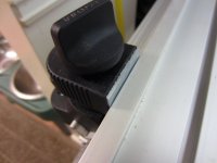
While setting up the MFT3, I misunderstood the directions on the stops preset at the factory for the guide rail supports. So, of course, I had to reset them which has been giving me much frustration. I finally settled on the idea of tightening the guide rail to the rear hinged support with the "preset" stop slid off toward the right side out of the way, actually both of the stops are loose and slid off toward the right end of the table. Then I lower the supports so the guide rail is sitting flush on the table top and use a combination square to align the already cut splinter guard exactly 8" from the right edge of the MDF top. I then slide the stops snugly against the supports and tighten them in place for future reference of supports. The problem I'm experiencing is that when I lift the guide rail on the hinged support and adjust the support height to accommodate the board thickness of the project piece and then flip the guide rail back down it will not "naturally" align with the front support notch into the guide rail. It's actually off a good3/8" to 1/2". I can pretty easily place it in the notch but you can certainly feel tension on the rear support hinge when forcing the rail into the notch. It holds fine and remains parallel to the side of the table, but in all the videos I'm watching it looks like they are just pretty much dropping the guide rail and it's aligning to the notch "naturally". I don't really see an adjustment on the hinge support to accommodate this mis-alignment unless I'm building the tension in by having the guiderail snugged onto the hinge support before aligning it parallel to the right edge of the table top. Could this be where I'm introducing the error?
There is a  ton for me to learn about these tools, and I really am not overly impressed with the manuals so far. Good thing for Festool this sight and the all the work many of the members here have put into youtube that I felt confident to make the purchase knowing I will get the answers. I will also mention that I've read and watched loads before making the decision to buy, but it's a bit different actually having the product in hand and using than reading and figuring in your head what's being demonstrated and explained.
Thanks in advance for any suggestions and solutions. Has anybody else had to readjust the stops. I know Greg Paolini says in his video that resetting the stops is no big deal, but he doesn't demonstrate that operation.
Jim
 
You have been bitten by the bug!  LOL.  Some tension is normal and my actually be desirable to offset any slight about of play at the front rail bracket.

Now that you have the MFT/3 the way I see it you have the choice to set it up two ways:

1.  The Festool way where everything is square and parallel to the extrusions; or
2.  Everything is square or parallel to the hole pattern.  

If you want to set it up the Festool way take a look at Steve Bace in these videos (my favorite) and pay attention to the rail to bracket mounting screws.  Also, your squaring aspect is done thru the adjustments on the fence mounting (which I usually call the protractor head)


If you want to go the parallel and perpendicular to the holes instead, then you will need to get a set of "dogs" and then set it up that way.  Lots of great videos out there on different ways to do that, I even have one where I have the feather keys removed and then reinstall.


Your choice, but my opinion is not to try and achieve both at the same time.

Peter
 
Exactly what I was looking for. I'm with you in regards to not caring whether I'm square to the frame rails or the MDF edges and holes, as long as I know I'm square at the guiderail to fence. I have to believe where I introduced my tension problem was in tightening the guiderail onto the hinged guide before setting up the straight edge. I'm presuming from the training school video that just as tightening the front hex screw on the hinge can create a problem, tightening both then aligning the front and rear supports from the edge put the guiderail itself in a bind. So if I loosen the guiderail to hinge screws, retighten the rear one with the fence aligned to the tab on the front support, then lift the hinged side and retighten the front screw, I suspecting I will eliminate the bind. At work this morning so will have to test the theory this evening. I'll post the results later tonight or tomorrow. Thanks for the thorough and quick response.
Jim
 
Peter Halle said:
Your choice, but my opinion is not to try and achieve both at the same time.

Peter

I'm not sure what you mean "not to try and achieve both at the same time." Do you mean in the same step? Once you have the extruded head parallel to the holes, then it's a fairly easy second step to square up the guide rail to that assembly. Not one step but does achieve both at the same time (so to speak). Am I missing something in the process that makes it difficult to square the head to holes and then the guide rail to the head?
 
Welcome, but, you do not have true green blood until you accidentally cut a really deep gouge in your MFT [scared]. 
Speaking of that, Greg Paolini gave me the best advice concerning which CMS to select.  He asked if I ever cut things the long way on the MFT.  If so, that shiny aluminum table on the CMS version that attaches to the MFS may get a very nasty slice.  I got to thinking about it and I would sure enough do that one day.  Now, all I need is a for all the stars to align into a combo Birthday/Christmas/Retirement present to buy one.

Ranny
 
Also, Be sure you have a square square.

If your square isnt truely square you'll be messing up a lot of cuts.

As your MFT set up will not be square

Dont ask me how I know that
 
jobsworth said:
Also, Be sure you have a square square.

If your square isnt truely square you'll be messing up a lot of cuts.

As your MFT set up will not be square

Dont ask me how I know that

+1

My MFT was off a little bit and I could not get it squared.  Finally I bought a Woodpeckers square to check the MFT.  I found the issue was my square.......
 
grbmds said:
Peter Halle said:
Your choice, but my opinion is not to try and achieve both at the same time.

Peter

I'm not sure what you mean "not to try and achieve both at the same time." Do you mean in the same step? Once you have the extruded head parallel to the holes, then it's a fairly easy second step to square up the guide rail to that assembly. Not one step but does achieve both at the same time (so to speak). Am I missing something in the process that makes it difficult to square the head to holes and then the guide rail to the head?

Sorry for the delay in responding.  I was referring to not trying to have the fence and rails parallel and perpendicular to the holes and also the table extrusions.

Peter
 
Peter, I understood that you meant not trying to square to both the extrusion and the MDF top at the same time, unless of course you've verified the top is in fact square to the extrusion. Anyways, Eureka! My problem was indeed induced by squaring the guide rail parallel to the side of the MDF top while having the guiderail to hinged support screws completely tightened. What happens is that I set the guiderail 8" from the right edge at the back of the table(measuring with a combination square) near the rear hinged support. I tightened the rear hinged support in place and slid the wedge stop against it and tightened the 3mm hex socket screw in the wedge in place. Then I moved the combination square towards the front of the table with the front of the guiderail notched to the front support with the tab in the guiderail channel as it should be. Of course, as I slid the front support towards the left to accommodate the 8" spacing from the right edge of the table it put the guiderail in a bind on the rear hinged support without my noticing. I then slid the front wedge stop snugly against the front support and tightened the 3mm head screw. From then on, if I lifted the guiderail off the front support and then allowed it to sit back down towards the table top, it would be offset @ the width of the tab that goes into the bottom channel of the guiderail. I could fairly easily force it back onto the notch and this would maintain the parallelism of the guiderail to the tableside, but it just didn't feel "right".
Tonight I started off loosening both of the guiderail to hinged support screws to allow the guiderail to relax. Laying it back in place, I found the guiderail almost 1/8" further from the table top side at the rear
support and dead nuts at the front. I actually had to readjust the rear support wedge stop and support that 1/8" closer to the right edge of the table top with the guiderail to hinged support screws still loose.
Then I tightened the rail to support rear screw from beneath as Greg Paolini or somebody's video demonstrates then carefully lifted the guiderail vertical and snugged the other rail to support screw. Now when I lower the guiderail it falls right onto the tab of the front support and I can slide the combination square set at 8" along and there is NO deviation between the splinterguard and combosquare blade.
Jim
 
You can set up your MFT/3 to get accurate, repeatable square cuts every time with just a few mods and tools.  Here's what I use:

1. Use two fence clamps instead of one clamp plus the angle/miter thing.
2. Add two layers of slick tape (UHMW) to each fence clamp where the small front face of the clamp butts against the back side of the fence.  This keeps the front edge of the fence from rising up.  This one modification really holds the fence tight against the MFT table.
3. Two dogs that fit in the MFT holes with minimal slop.
4. Slop Stop for the front rail clamp.
5. Large square.  I use an 18" Woodpecker triangle.

Then, use Paul Marcel's videos to make a calibration block for the flag stop.  Use the dogs and large square to square the fence to the holes.  Then, square the rail to the fence.  I had to move the front rail clamp slightly from the factory position to get mine square.

Now it is bullet proof and easy to set up and check squareness any time I want.
 
I can't get my head around the two layers of slick strip.  Can you take a picture?  Honestly I would love to see any pictures of your setup.  It might help others.

Peter
 
Peter Halle said:
I can't get my head around the two layers of slick strip.  Can you take a picture?  Honestly I would love to see any pictures of your setup.  It might help others.

Peter

I knew someone was going to ask that.  ;D

[attachthumb=#]

Hopefully, you can recognize the whitish looking slick tape between the clamp and the fence.  It takes two layers of slick tape to fill the gap between the clamp and the rail.  Otherwise, the gap allows the front edge of the rail to rise up a considerable amount.  I think Paul Marcel mentions this problem in his video.
 

Attachments

  • IMG_0143.JPG
    IMG_0143.JPG
    822.8 KB · Views: 404
SoonerFan said:
jobsworth said:
Also, Be sure you have a square square.

If your square isnt truely square you'll be messing up a lot of cuts.

As your MFT set up will not be square

Dont ask me how I know that

+1

My MFT was off a little bit and I could not get it squared.  Finally I bought a Woodpeckers square to check the MFT.  I found the issue was my square.......

Thats what I did, after a lot of curseing and frustration thinking I did everything right , looked at the set up videos over and over and nothing came out right.

I took a end users class emailed Steve with my issue, He assured me I would understand how to set up the MFT after it.
It all came down to me not having a good true square square.

Got the woodpeckers square and life was good. Solved the world problems including My worlds Peace....

From a lot of the post here it has boiled down to the same issue.

A unsquared square.
 
grbmds said:
Peter Halle said:
Your choice, but my opinion is not to try and achieve both at the same time.

Peter

I'm not sure what you mean "not to try and achieve both at the same time." Do you mean in the same step? Once you have the extruded head parallel to the holes, then it's a fairly easy second step to square up the guide rail to that assembly. Not one step but does achieve both at the same time (so to speak). Am I missing something in the process that makes it difficult to square the head to holes and then the guide rail to the head?

I wont talk about the nice kerf in my MFT fence and a similar looking one in the V channel on my MFT to.

They just magically appeared one day
 
jbair said:
Peter, I understood that you meant not trying to square to both the extrusion and the MDF top at the same time, unless of course you've verified the top is in fact square to the extrusion. Anyways, Eureka! My problem was indeed induced by squaring the guide rail parallel to the side of the MDF top while having the guiderail to hinged support screws completely tightened. What happens is that I set the guiderail 8" from the right edge at the back of the table(measuring with a combination square) near the rear hinged support. I tightened the rear hinged support in place and slid the wedge stop against it and tightened the 3mm hex socket screw in the wedge in place. Then I moved the combination square towards the front of the table with the front of the guiderail notched to the front support with the tab in the guiderail channel as it should be. Of course, as I slid the front support towards the left to accommodate the 8" spacing from the right edge of the table it put the guiderail in a bind on the rear hinged support without my noticing. I then slid the front wedge stop snugly against the front support and tightened the 3mm head screw. From then on, if I lifted the guiderail off the front support and then allowed it to sit back down towards the table top, it would be offset @ the width of the tab that goes into the bottom channel of the guiderail. I could fairly easily force it back onto the notch and this would maintain the parallelism of the guiderail to the tableside, but it just didn't feel "right".
Tonight I started off loosening both of the guiderail to hinged support screws to allow the guiderail to relax. Laying it back in place, I found the guiderail almost 1/8" further from the table top side at the rear
support and dead nuts at the front. I actually had to readjust the rear support wedge stop and support that 1/8" closer to the right edge of the table top with the guiderail to hinged support screws still loose.
Then I tightened the rail to support rear screw from beneath as Greg Paolini or somebody's video demonstrates then carefully lifted the guiderail vertical and snugged the other rail to support screw. Now when I lower the guiderail it falls right onto the tab of the front support and I can slide the combination square set at 8" along and there is NO deviation between the splinterguard and combosquare blade.
Jim

My guide rail does not fall directly onto the tab on the front support either.  I thought that there was supposed to be tension on it and that it was designed so that you had to move the rail over slightly for the tab on the front support to fit into the rail's groove?

Anyone know for sure what Festool's intent is...A) Rail drops directly onto the tab or B) move the rail slightly so that there is some tension?
 
Seems as if there are multiple ways to actually get things square. I definitely prefer the concept of getting the miter fence (extrusions) parallel to the MFT/3 holes. This allows a lot of flexibility to use dogs to cut 45 degree angles plus facilitates other cuts. After that, it really isn't that hard to get the guide rail square to the miter fence with a good square square. My problem is that it doesn't seem to stay that way for very long. I check the squareness almost every time I do work on the MFT/3 table and find that the rail is no longer square to the miter fence; sometimes the fence isn't parallel to the holes either. This puzzles me.
 
grbnds, I think it's those damned gremlins that cause that going out of square business. And I agree the holes are a reliable method, I just haven't splurged for the qwasdogs or parf dogs or any of the other dogs yet. Quite honestly, I was using the stops that came with the clamping elements package I did splurge on. The problem was I was getting frustrating results because I threw the whole deal off when I loosened and moved the factory preset wedge stops in the rails before anything else, and none of the videos I'd came across addressed "how" to reset them. The edge of the table just appeared a reliable and repeatable method for me. Since the top is CNC machined, I'd be surprised if the rows and columns of holes were not square and parallel to the edges of the top. I'll check that just our of curiosity and report back. I have found squaring the fence was idiot proof, since even this idiot mastered that task.
Jim
 
I know others have eluded to this but the beauty of the mft is the holes! Once I switched to the holes as the starting point my table became much more used. Makes a really nice router system with the track and dogs too.
 
Back
Top