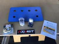
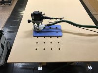
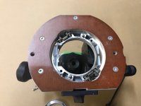
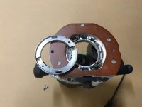
So I received the Dominofix from the Toolnut a couple days ago and finally put it to use this morning. I was very impressed with the quality and fit of the Festool 30mm guide bushing (purchased) and template dogs that came with it .. all fit tight and lined up perfectly to my Festool Kapex top I used for reference. Then a problem .. I had purchased the centering Mandrel to make sure the guide bushing was perfectly centered and soon realized there is no way to adjust the snap-in guide bushing on the OF1400. My oversight, but I haven't used the router much and never had a guide bushing on it. I checked here on the FOG and realized this has been a subject in the past. I went ahead and punched 6 rows of holes and then turned the template to punch some holes across the top ... no bueno! The template dogs wouldn't lock in to the existing holes so I checked alignment with my Woodpeckers MFT square and Kapex Top and realized holes were off slightly. I'm fairly certain the guide bushing is off center ever so slightly, but "ever so slightly" is quite a bit when requiring accurately spaced holes. I'm not ready to give up yet as I was impressed with the speed I could punch out a top and everything else about the system, but needs to be accurate. My old Bosch plunge router is at my son's house in another State, so kind of dead in the water right now unless I want to buy another router .. one I can adjust/center the guide bushing. Looking for suggestions if I'm missing something here?
You are using an out of date browser. It may not display this or other websites correctly.
You should upgrade or use an alternative browser.
You should upgrade or use an alternative browser.
MFT Hole Jigs
- Thread starter Grev
- Start date

Cheese
Member
The Dominofix doesn't require the router to be moved because it bores a 20mm hole straight away. So just position the 1400 in the same position for every hole and don't turn the template. That way if there is a problem with the boring bit and template concentricity, the small amount of offset will always be in the same direction.
Cheese said:The Dominofix doesn't require the router to be moved because it bores a 20mm hole straight away. So just position the 1400 in the same position for every hole and don't turn the template. That way if there is a problem with the boring bit and template concentricity, the small amount of offset will always be in the same direction.
I realize what you're saying .. I just plunged the router straight down and held it in the same orientation for every hole, however, if you want more than a 4 hole pattern across your sheet, it is necessary to pivot the Dominofix 90 degrees and begin plunging at a right angle to the initial grid. That's where the problem is ... the 2 Dominofix retaining dogs would not insert into the holes I just routed because they were off slightly. Should be able to place the template in any direction on the grid pattern and have the 20 mm dog holes line up ... which it did on my Kapex MFT. Bottom line, to use this system and get the accuracy of 96mm grid pattern, you need to be able to adjust your routers baseplate/guide bushing with a centering mandrel ... can't do it with the OF 1400.
Cheese
Member
I don't have a Dominofix so maybe there's something I'm not understanding.
If you place the entire first row of holes across the bottom of the material, always moving the jig from left to right and never rotating it, why can't you do the same with the 2nd row and the remaining rows?
If you place the entire first row of holes across the bottom of the material, always moving the jig from left to right and never rotating it, why can't you do the same with the 2nd row and the remaining rows?
Michael Kellough
Member
[member=44099]Cheese[/member] the plan is that you rotate the jig 90* to space the next row correctly. Punch 2 holes then rotate back to continue the row.
It seems like maayybbee if the router/offset bushing is also rotated the right way to compensate it might work. But I’m sure TTG already tried that...
It seems like maayybbee if the router/offset bushing is also rotated the right way to compensate it might work. But I’m sure TTG already tried that...
Cheese
Member
Michael Kellough said:[member=44099]Cheese[/member] the plan is that you rotate the jig 90* to space the next row correctly. Punch 2 holes then rotate back to continue the row.
It seems like maayybbee if the router/offset bushing is also rotated the right way to compensate it might work. But I’m sure TTG already tried that...
Thanks Michael...well that's kind of goofy, that just adds tolerancing stacking issues to the equation. So rather than rotating 180º, why not try flipping the jig upside down. That way the left-to-right geometry stays the same and the only potential issue is any slight differences between the rows.
Michael Kellough
Member
[member=44099]Cheese[/member] this is getting beyond my understanding of the jig (not having one) but it seems like you’d need a pair of 30x20 dogs to align a flipped over jig with...
Could be totally wrong.
Could be totally wrong.
Michael Kellough
Member
gnlman said:Hmm I've only taken my base plate off once to use it as a template for a circle jig...it seems to me that there are some screws under the fiber baseplate....I'll check when I get home I thought that was how you adjusted the template bushing.....
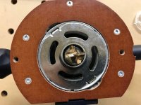
I hope you’re right! Offset shown in the photos is unacceptable. I don’t have a 1400 router but I can’t believe it has to be that bad.
[member=63307]TrackTubesGuy[/member] I recall someone posting recently that there are two screws holding the metal piece on the base plate (that the template clips into). This person drilled two access holes through the template to access those screws so they could be loosened and retightened while the centering mandrel is installed. That allowed him to get the template centered properly.
Cheese
Member
Michael Kellough said:[member=44099]Cheese[/member] this is getting beyond my understanding of the jig (not having one) but it seems like you’d need a pair of 30x20 dogs to align a flipped over jig with...
Could be totally wrong.
Hey Michael, for the “second” row of holes, the jig would be clamped to the material, the newly drilled holes would be 20 mm in diameter.
For the “first” row of holes, the jig would be flipped over and the 20 mm dogs would align with the new drilled holes and also align in the Dominofix.
I used some of the same methods on the Woodpeckers jig. Always moving the jig only left to right and always pushing the jig in the same direction before clamping it down. Once the jig was moved and the dogs installed, it was pushed up and to the left before reclamping.
This really minimized any tolerance stacking. I drilled 12 holes and the theoretical center to center distance between the first and the last was 1056 mm. When I measured mine the distance was 1057 mm.
rvieceli
Member
[member=44099]Cheese[/member] check my logic here please. It would seem that even not centered perfectly, if you keep the router in the same orientation throughout the process the holes should be accurate.
The problem seems it might be keeping the router aligned to the jig when the jig is flipped 180. So if you were keeping the handle on the 1400 pointed right and parallel to the long edge. When you rotated the jig 180 to bore the second row, you would rotate the router handle to the left so that it would keep the orientation consistent.
Ron
Cheese
Member
RKA said:[member=63307]TrackTubesGuy[/member] I recall someone posting recently that there are two screws holding the metal piece on the base plate (that the template clips into). This person drilled two access holes through the template to access those screws so they could be loosened and retightened while the centering mandrel is installed. That allowed him to get the template centered properly.
Hey Raj, along with the 2 screws under the copy ring, there are also 2 alignment dowels. Those dowel alignment holes would also have to be enlarged. Or the alignment dowels removed.
Worse yet though, because the copy ring isn’t actually fastened to anything and only snugged down by a couple of quick release clamps, the copy ring can be moved .010-.015” perpendicular to the axis created by the 2 quick release clamps. [sad]
I learned something...use the 1010 when you need precise placement.
Cheese
Member
Hey Ron, you’ve got the logic down pat. [big grin]
Even if the concentricity was off by .030” keeping everything aligned and always keeping the tolerance difference in the same direction essentially mitigates the issue if you’re careful. That’s also where Michael was going. [smile]
A problem though is having to turn the jig 90 or 180 degrees. If always sliding one direction, all the tolerance is in one axis. Turning the jig now now puts two axis of tolerances into play.
Cheese said:RKA said:[member=63307]TrackTubesGuy[/member]
Hey Raj, along with the 2 screws under the copy ring, there are also 2 alignment dowels. Those dowel alignment holes would also have to be enlarged. Or the alignment dowels removed.
Worse yet though, because the copy ring isn’t actually fastened to anything and only snugged down by a couple of quick release clamps, the copy ring can be moved .010-.015” perpendicular to the axis created by the 2 quick release clamps. [sad]
I learned something...use the 1010 when you need precise placement.
You're absolutely right ... would need to drill out the screw holes in the removable part, drill out the alignment pin holes, and even then probably would not move much because of how tight it fits in the cast base. Not going there .. might have to check out the 1010 ... or a Bosch.
Attachments
Hmmmm I have this dominofix coming as well....was going to pick up the 30mm guide bushing and a mandrel...guess there is not much point getting a mandrel for my OF1400.....I took my base of when I got home...same results...no adjustment. My guide bushing that came with the router however is very snug...like many, I've only used a guide bushing in a circle jig I built, and then used a porter cable style bushing with the adapter bushing that came with the router....not a very expensive set, but circles turned out fine...I guess we'll see how accurate it is when I drill the holes...and hope....very disappointing. I'll try and pick up the 30mm guide bushing tomorrow if my local store has one and I'll give it a look and post what I find.....
I really like this router..have bought lots of accessories for it....what other router can you buy that will accept metric guide bushings, that can be centered....bosch??
Greg
I really like this router..have bought lots of accessories for it....what other router can you buy that will accept metric guide bushings, that can be centered....bosch??
Greg
waho6o9
Member
Maybe this might help in centering the mandrel and router bit:
waho6o9 said:Maybe this might help in centering the mandrel and router bit:
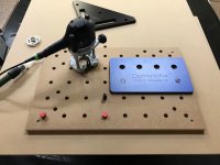
Thanks for this ... I fiddled with the base again this evening and realized you can pull the indexing pins out with a pair of needle nose pliers ... gives the guide bushing adapter plate a little more play/adjustment, but not much. I punched another 4 grid pattern and was better, but still off a little. You would have to notch the plate as shown in the video to tighten the screws when centered. At this point I'm thinking of working on a custom base for the 1400 that would accept Porter Cable style guide bushings (like the one Jasper Tools sells) ... I'm not giving up on this yet.
Cheese
Member
TrackTubesGuy said:Thanks for this ... I fiddled with the base again this evening and realized you can pull the indexing pins out with a pair of needle nose pliers ...
Truth be told...this is not a good alternative. While I have been vitriolic in some of the Festool generated solutions, this is not a good path to follow. Festool went to the extra effort to install those indexing pins at a substantial effort to index the ring correctly. It doesn’t make any sense to me but there must be some justification to their rationale. These are truly the times where Festool customer service would weigh in and right the ship. [member=57769]TylerC[/member] ...any info would be good info.
Similar threads
- Replies
- 58
- Views
- 3K
- Replies
- 10
- Views
- 561