MFT template for custom tops.

anthonyz

Retailer
Member
Joined
May 24, 2014
Messages
388
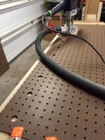
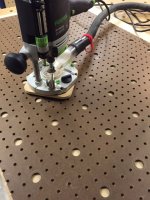
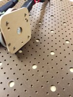
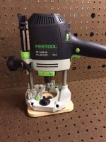
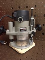
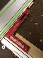
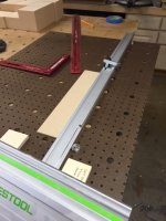
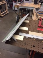
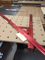
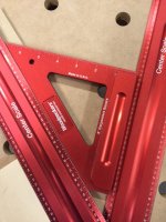
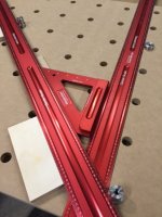
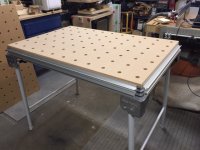
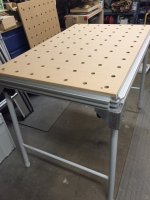
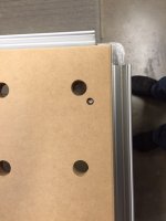
Been working on a template for cutting my own MFT tops. It is based on 20mm holes 4" on center, using a technique I heard here on FOG using a pegboard for alignment. You can see the Template Jig which fits on my OF1400. I also included holes for the Porter Cable Plunge for someone who doesn't have an Festool router. Pins on the bottom align it on the 1/4" hole peg board. Works great to set aligned holes into a custom MFT top. I laid out a peg board with the 20mm holes which is sized for a MFT table. I can just lay in out on a MFT slab cut to size and cut my holes. I can also cut tables of any size with this set up and a larger piece of Peg board. Wondering if others would have an interest in this Jig plate if I could make it available? The plate is CNC'd for accuracy of the hole layout.
 

Attachments

  • IMG_3100.JPG
    IMG_3100.JPG
    231.6 KB · Views: 8,026
  • IMG_3101.JPG
    IMG_3101.JPG
    235.9 KB · Views: 7,834
  • IMG_3102.JPG
    IMG_3102.JPG
    220.7 KB · Views: 10,040
  • IMG_3093.JPG
    IMG_3093.JPG
    224.3 KB · Views: 5,046
  • IMG_3087.JPG
    IMG_3087.JPG
    198.9 KB · Views: 4,629
Anthony

That is fantastic! 

Quick question. In the first photo, it looks like you plunged the router with a smaller bit before using the 20mm. Am I correct?

Do you have a video showing this in use? 

 
Wooden Skye said:
Anthony

That is fantastic! 

Quick question. In the first photo, it looks like you plunged the router with a smaller bit before using the 20mm. Am I correct?

Do you have a video showing this in use? 
I first laid out the peg board with where I would bore the 20mm holes. The holes you see being bored are the 20mm holes. You could do 3/4 holes with this jig too for those wanting imperial. I don't have a video as of yet, but I hope to work on one soon, to show how to use it. If I have enough interest, I will see what it will cost to do a production run and shipping. As I don't think 1/4" peg board is available outside of the US, This would probably be only NAATUS (Not Available Anywhere, but The United States).
 
I assume you verified that the pegboard holes were actually accurate? Since I depend on the holes being in line and at 90 degrees to use the MFT fence and guide rail, I would think I'd need to verify that. I know some don't use the fence and guide rail and, instead, just use the dogs as a fence, etc. I would still be important, though, to know that the pegboard holes were precise, wouldn't it?
 
This would be most ideal for people who want a custom MFT style top for clamping or those who use a square to set up their MFT table rather than qwas dogs. The Pegboard is pretty square, BUT since it in not cnc's there can be tiny error. Also, if the person plunge cutting the tables, did not seat the router on one of the cuts it could also throw something off. Of course if there is any flaws in the pegboard that would translate into the top. As people would be responsible for their own peg board there is the possibility of slight variations. I am planning on a couple Tops and will hopefully get them made in the next week. I have a couple of ideas which should help reduce if there are any slight variations in the peg board materials. This WOULD BE a viable option for those who use a square to align their track to their fence or those who are planning on building a table more for clamping than a cutting table. I will update info on the accuracy as I learn more.

Thanks for asking.

grbmds said:
I assume you verified that the pegboard holes were actually accurate? Since I depend on the holes being in line and at 90 degrees to use the MFT fence and guide rail, I would think I'd need to verify that. I know some don't use the fence and guide rail and, instead, just use the dogs as a fence, etc. I would still be important, though, to know that the pegboard holes were precise, wouldn't it?
 
The MFT3 tops also have a perfect 45 degree matrix built in the system

as well, so that should be checked when time allows.

I thought my Walko4 had a 45 degree matrix built in but I was wrong.

Oops.
 
anthonyz said:
This would be most ideal for people who want a custom MFT style top for clamping or those who use a square to set up their MFT table rather than qwas dogs. The Pegboard is pretty square, BUT since it in not cnc's there can be tiny error. Also, if the person plunge cutting the tables, did not seat the router on one of the cuts it could also throw something off. Of course if there is any flaws in the pegboard that would translate into the top. As people would be responsible for their own peg board there is the possibility of slight variations. I am planning on a couple Tops and will hopefully get them made in the next week. I have a couple of ideas which should help reduce if there are any slight variations in the peg board materials. This WOULD BE a viable option for those who use a square to align their track to their fence or those who are planning on building a table more for clamping than a cutting table. I will update info on the accuracy as I learn more.

Thanks for asking.

grbmds said:
I assume you verified that the pegboard holes were actually accurate? Since I depend on the holes being in line and at 90 degrees to use the MFT fence and guide rail, I would think I'd need to verify that. I know some don't use the fence and guide rail and, instead, just use the dogs as a fence, etc. I would still be important, though, to know that the pegboard holes were precise, wouldn't it?

Thanks for the response. I understand the possible movement when making the holes with the router regardless of how careful. I made a workbench and drilling 3/4"  dog holes for regular dogs was a difficult proposition and they never did get exact. It wasn't a problem for that use but, for this use, it's much more important. I will be interested in the result and how exact it gets.
 
I set up a small 32" track with rail dogs, Place two parff dogs to square the fence to the track (in the pegboard template). After placing my 12" woodpecker square in the corner. I was happy to see no play in the angle. With the jig having 4 pins spread 4" apart and they fit into the pegboard consistently it says things are pretty square in the pegboard.

I will try this again and test the square in the final table and report back. So far things are looking good.
grbmds said:
anthonyz said:
This would be most ideal for people who want a custom MFT style top for clamping or those who use a square to set up their MFT table rather than qwas dogs. The Pegboard is pretty square, BUT since it in not cnc's there can be tiny error. Also, if the person plunge cutting the tables, did not seat the router on one of the cuts it could also throw something off. Of course if there is any flaws in the pegboard that would translate into the top. As people would be responsible for their own peg board there is the possibility of slight variations. I am planning on a couple Tops and will hopefully get them made in the next week. I have a couple of ideas which should help reduce if there are any slight variations in the peg board materials. This WOULD BE a viable option for those who use a square to align their track to their fence or those who are planning on building a table more for clamping than a cutting table. I will update info on the accuracy as I learn more.

Thanks for asking.

grbmds said:
I assume you verified that the pegboard holes were actually accurate? Since I depend on the holes being in line and at 90 degrees to use the MFT fence and guide rail, I would think I'd need to verify that. I know some don't use the fence and guide rail and, instead, just use the dogs as a fence, etc. I would still be important, though, to know that the pegboard holes were precise, wouldn't it?

Thanks for the response. I understand the possible movement when making the holes with the router regardless of how careful. I made a workbench and drilling 3/4"  dog holes for regular dogs was a difficult proposition and they never did get exact. It wasn't a problem for that use but, for this use, it's much more important. I will be interested in the result and how exact it gets.
 

Attachments

  • IMG_3107.JPG
    IMG_3107.JPG
    218.8 KB · Views: 3,240
  • IMG_3106.JPG
    IMG_3106.JPG
    206.3 KB · Views: 3,501
  • IMG_3105.JPG
    IMG_3105.JPG
    222.3 KB · Views: 5,625
I added a video with doing the layout and making an MFT top using the template and the pegboard.


anthonyz said:
Wooden Skye said:
Anthony

That is fantastic! 

Quick question. In the first photo, it looks like you plunged the router with a smaller bit before using the 20mm. Am I correct?

Do you have a video showing this in use? 
I first laid out the peg board with where I would bore the 20mm holes. The holes you see being bored are the 20mm holes. You could do 3/4 holes with this jig too for those wanting imperial. I don't have a video as of yet, but I hope to work on one soon, to show how to use it. If I have enough interest, I will see what it will cost to do a production run and shipping. As I don't think 1/4" peg board is available outside of the US, This would probably be only NAATUS (Not Available Anywhere, but The United States).
 
I am starting a small production run of these. I should know more next week on pricing and such, waiting on hardware I had to order. I will set up a small website for ordering. I will post in this thread and Also on the video page.

Thank for your interest!

SteveZ said:
I'd be interested in a template also.
SteveZ
 
waho6o9 said:
The MFT3 tops also have a perfect 45 degree matrix built in the system

as well, so that should be checked when time allows.

I thought my Walko4 had a 45 degree matrix built in but I was wrong.

Oops.

It was dead on accurate 45' No play. More and more happy with the results. Moving forward with a small production run. Laid it out with parff dogs and woodpecker rulers. 
 

Attachments

  • IMG_3128.JPG
    IMG_3128.JPG
    211.6 KB · Views: 4,961
  • IMG_3127.JPG
    IMG_3127.JPG
    252 KB · Views: 1,850
  • IMG_3126.JPG
    IMG_3126.JPG
    230.1 KB · Views: 1,846
If you don't mind telling, what are you using for the 1/4 "pins" that mate with the pegboard?
 
I couldn't find this answer . . . Is the top designed to replace the top in an MFT table? Or is your focus a custom size top?
 
grbmds said:
I couldn't find this answer . . . Is the top designed to replace the top in an MFT table? Or is your focus a custom size top?

Both, I put my new top on this morning. Depending on how you lay out the hole pattern on your MFT replacement top, since it is 4" on center rather than 96mm the spacing will be different. I had to make new mounting holes because I wanted to maximize the number of holes. If I did one less row, I would not have had to make new mounting holes on my MFT base. The corner holes on mine are blocked on the bottom, but since I use Parff dogs which are short, they work fine in the top. Just can't run clamps through those corner holes other than element clamps. Here is the new top on my MFT. Note this is using Ultra light MDF at $30-$35 a sheet. Original top weight 24lbs, new top weight 14lbs. 10 lbs lighter. what a difference if you move it like I do. 
 

Attachments

  • IMG_3129.JPG
    IMG_3129.JPG
    203 KB · Views: 2,201
  • IMG_3130.JPG
    IMG_3130.JPG
    188.1 KB · Views: 1,625
  • IMG_3131.JPG
    IMG_3131.JPG
    156.7 KB · Views: 1,777
I have been thinking about making one of these plates myself (finding a CNC guy)  You just saved me the hassle and should be less expensive then doing only 1.

I am interested.  Great idea.  Keep me posted.
 
Capt'n 360 said:
I have been thinking about making one of these plates myself (finding a CNC guy)  You just saved me the hassle and should be less expensive then doing only 1.

I am interested.  Great idea.  Keep me posted.

I should have them available starting next week. Have the templates being Cnc'd and waiting on the hardware. I will be including screws for the Festool OF1400 to mount the plate. For people using a porter cable base, they can use their pre-exisiting screws. Estimated price will be $32+Shipping and handling. 
 
Anthony,
Is the 20 mm bit you are using a hinge boring bit? I have found those drill a 20.2 mm hole which is a bit loose for my taste. I have found 20mm forester bits which are true to size but they are meant for drills and not routers. It wasn't clear to me if they would be safe to use in a router.
 
Back
Top