Motivation
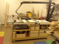
I recently replaced my pimped out Ryobi BT3K with a Sawstop PCS. My BT3K setup had 2 sets of rails with an extended table to the right of the blade. The extension table included a woodpecker PRL router plate.
[attachthumb=#]
However, there were 2 aspects of my extension table that I did not like.
The Sawstop PCS shipped with a simple flat extension table. The motivation for this project was to regain the router plate while correcting the 2 issues above.
[attachthumb=#]
Full Goals
I recently replaced my pimped out Ryobi BT3K with a Sawstop PCS. My BT3K setup had 2 sets of rails with an extended table to the right of the blade. The extension table included a woodpecker PRL router plate.
[attachthumb=#]
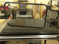
However, there were 2 aspects of my extension table that I did not like.
- there was no way to clamp or fix workpieces to the top,
- the top was built into the cabinet and was not replaceable (and I had mistakenly cut into it multiple times)
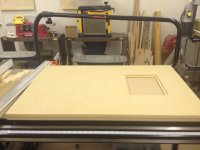
The Sawstop PCS shipped with a simple flat extension table. The motivation for this project was to regain the router plate while correcting the 2 issues above.
[attachthumb=#]
Full Goals
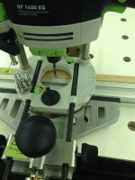
- Create router table
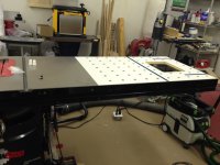
- Clamping/fixturing options
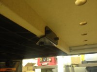
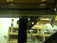
- No new holes in sawstop hardware
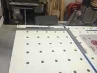
- Modular/replaceable top
- Flatter than sawstop table
- Minimize cost
- Allow for future expansion (dust box and router bit storage)