Parallel Guide Jig on MFT Top

spoonik

Member
Joined
Jul 4, 2021
Messages
5
Hello everyone, 

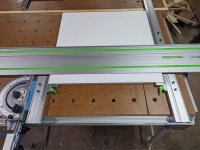
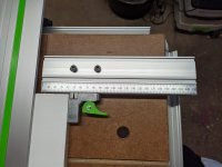
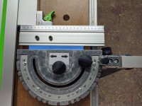
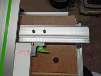
Long time lurker first time member and poster. I came up with a jig / mounting solution for putting the Parallel guides extensions (FS-PA-VL) onto a an MFT Top (with 96 mm hole spacing)
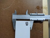
It makes repeatable narrow rips very easy and quick.

I already had the Parallel guides but haven't used them since getting my MFT/3. I wanted to try to reuse what I already had. Let me know your feedback, want to hear what the community thinks  [big grin]

Pictures are attached


Attachments

  • PXL_20210703_202855012.jpg
    PXL_20210703_202855012.jpg
    732.4 KB · Views: 746
  • PXL_20210703_202905523.jpg
    PXL_20210703_202905523.jpg
    619.4 KB · Views: 539
  • PXL_20210703_202912597.jpg
    PXL_20210703_202912597.jpg
    661.5 KB · Views: 505
  • PXL_20210703_203020745.jpg
    PXL_20210703_203020745.jpg
    631.6 KB · Views: 454
  • PXL_20210703_203106892.jpg
    PXL_20210703_203106892.jpg
    693.2 KB · Views: 449
  • PXL_20210703_203123599.jpg
    PXL_20210703_203123599.jpg
    616.3 KB · Views: 419
Michael Kellough said:
Is this going to result in one new kerf in the mdf or a new kerf for every cut?

If I understand what you mean new kerf for every cut. The track doesn't move, so cut in the MDF is the same.

Things cut on the right side of the track will always have the kerf included, but that's accounted for by the FS-PA-VL system if calibrated properly. So when you set it to 5 cm you get 5cm.

Hope that makes sense  [smile]

Edit, the training video from Festool explain how the FS-PA-VL system works, if you're unfamiliar.
 
Maybe I’m missing something. How a did you attach them to the MFT?

Looking at the pictures posted, it looked as if the measurement was 42mm, but your final piece was like 47.5mm. That doesnt seem right. Also, the arrows look they are at 51mm.

Something isn’t adding up right.

Sent from my iPhone using Tapatalk
 
Jason Hagen said:
Maybe I’m missing something. How a did you attach them to the MFT?

Looking at the pictures posted, it looked as if the measurement was 42mm, but your final piece was like 47.5mm. That doesn’t seem right. Also, the arrows look they are at 51mm.

Something isn’t adding up right.

Sent from my iPhone using Tapatalk

Thanks for the comment.

The guides are attached via 3D printed adapters. The top one is static so it uses two 20 mm dogs and just screws in. It can slide back and forth laterally using a T-slot and T-nuts, so you can calibrate it with the blade kerf.

The bottom guide needs to slide based on the dimensions of the workpiece, so I used the sliding protractor and designed an adapter plate to connect the protractor to the guide. The bottom guide also has a T-slot and T-nuts so it can slide for kerf calibration.

I believe you have misread things regarding the measurements. The guides were set to 5 cm, which admittedly is hard to read, but that's the system Festool came up with. My calipers read 5 cm as well if you look at the 0 with the line. Please see attached images for clarification.
 

Attachments

  • PXL_20210703_202905523.jpg
    PXL_20210703_202905523.jpg
    711.4 KB · Views: 366
  • PXL_20210703_203106892.jpg
    PXL_20210703_203106892.jpg
    670 KB · Views: 327
Back
Top