Parf Guide mark 2 issues and questions

wch

Member
Joined
Dec 16, 2018
Messages
7
I recently got my Parf Guide Mark II system, and I have some issues and questions.

First off, it looks like one of the Parf sticks has hole spacing that is ever-so-slightly greater than the other. The error is such that over the 960mm from hole 0 to hole 10, one stick has holes that are around 0.10-0.15mm farther apart than the other one. Has anyone else encountered this before?

My grid is 15 wide by 7 high. When using the Parf sticks to make the "starter" set of 11x7 holes, it worked out OK. Next, I extended the grid to the right by adding 4 holes to the top row and 4 holes to the bottom row. Then I tried to connect the far-right top and bottom holes by pinning one of the Parf sticks to the top-right hole and bottom-right hole. Unfortunately, the 3mm holes I drilled in the table were slightly too far apart, and the pins wouldn't seat all the way. I think this is because the 3-4-5 triangle that was used to create the grid was slightly off, resulting in a grid that wasn't quite square.

I'm concerned that with the slight error of the holes, when I try to cut a right angle, the angle could be off by an amount that will cause problems when I try to do precise work. Is that a reasonable concern? I watched Peter Parfitt's video where he found that cuts on the workbench he made had an error of about 0.03 degrees per cut, which is very good.

Incidentally, the fact that I'm encountering fit problems when the error is so small is a testament to the overall precision of the Parf Guide system.

I have a few other questions that hopefully someone here can help answer. These first two relate to how close to perpendicular the holes will be.

  • How accurate can I expect the hole spacing to be on the underside of the panel?
  • For taller dogs like Super Dogs, how accurate can I expect them to be further away from the table?
  • The panel I'm using is MDO, based on the recommendation of someone from this forum. Unfortunately, it's slightly bowed so that if one end is pressed all the way down, the other end will stick up probably half an inch. Is unreasonable to expect an MDO panel to be much flatter than this?

Here are some pictures that show the misalignment of the holes.

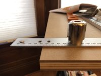
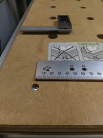
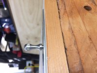
With the fixing pin connecting both Parf sticks at hole 0, the longer drill guide seats easily all the way into hole 1.

View attachment 1

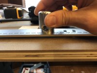
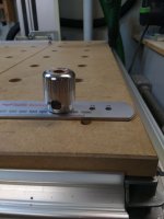
With the fixing pin still at 0, the drill guide fits tightly in hole 5. In this picture, it's tight enough that I'm able to lift both Parf sticks off the table with the friction.

View attachment 2

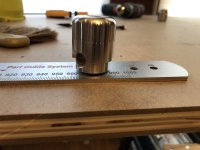
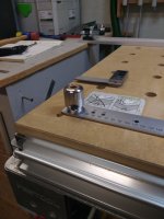
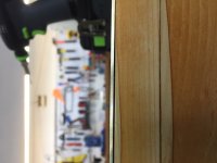
With the fixing pin still at 0, the drill guide won't go through both Parf sticks at hole 10.

View attachment 3

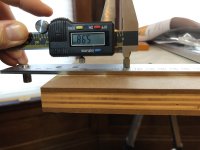
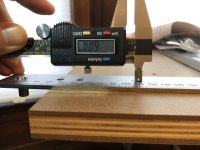
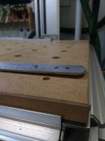
Using calipers going through both Parf sticks at hole 1, I measured a width to be 5.98mm.

View attachment 4

If I lift the calipers slightly so that it's engaging the hole in only one of the Parf sticks, the width is 6.00mm.

View attachment 5

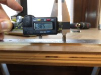
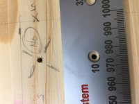
At hole 10, going through both Parf sticks, the width is 5.86mm.

View attachment 6

At hole 10, lifting the calipers slightly so that it engages the hole in only one Parf stick, the width is 5.99mm.

View attachment 7
 

Attachments

  • IMG_5770.JPG
    IMG_5770.JPG
    276.1 KB · Views: 2,507
  • IMG_4903.JPG
    IMG_4903.JPG
    312 KB · Views: 1,809
  • IMG_8415.JPG
    IMG_8415.JPG
    300.1 KB · Views: 1,509
  • IMG_8797.JPG
    IMG_8797.JPG
    307.4 KB · Views: 1,626
  • IMG_4561.JPG
    IMG_4561.JPG
    311.8 KB · Views: 1,267
  • IMG_2319.JPG
    IMG_2319.JPG
    326.9 KB · Views: 1,230
  • IMG_8020.JPG
    IMG_8020.JPG
    339.1 KB · Views: 1,415
This is something that Axminster will sort out and the OP is now aware that that is the best route to take if there is any suspicion of a faulty part.

Peter
 
I contact Axminster about the issue and they must have agreed that the ones pictured above are defective, because they promptly shipped out some replacement Parf sticks.

tallgrass, I don't have any gauge pins, but I believe that, based on my measurements, the holes themselves are within 0.02mm of 6.00mm -- it's just that they're not spaced exactly the same on both Parf sticks, so that that when the two sticks are on top of each other and registered at hole 0, the further you get from hole 0, the more out of alignment the holes get.
 
I am sure you are correct. I was just curious. measuring holes accurately with Veneers can be fiddly. I always suggest when people get calipers or veneers, they should get a reference block, small surface plate and a set of pins.

These kind of jigs can have horrendously difficult tolerances to measure accurately. Especially when dealing with something like this. I am always impressed with these various solutions and how "accurate" they are, especially when dealing with the implications of accumulative error. Sounds like they handled it well.
 
box185 said:
Side by side, the metric scales are different between the original Parf stick and the Mark II Parf stick - not sure yet about the hole spacing. Other than a relative comparison, I also do not know which one is more accurate. Does any of this matter?

The metric scales are not relevant to the function f the tool and were put there as a bonus. If you go into any store and take rules and tape rules and compare them you will find variation between manufacturers. That is why one is encouraged to use just one for the duration of a project.

I have covered all of this in my "Measuring and Marking video from a while back:


The Original PGS and the PGS Mark 2 are expected to produce the same degree of accurate layouts of 20 mm holes. The Mark 2 will last longer as there are no moving parts to wear out the Parf Sticks.

Peter
 
The scale on the 'stick' seems like something of a distraction in this matter.

What is important (for the resulting "squareness" or "perpendicularity" of the resulting hole pattern), however, is that the spacing between the holes is consistent - and that the two sticks used are identical. The former is a matter of pre-production planning; the latter would seem to be virtually guaranteed (barring some highly bizarre circumstances in production). If either of those conditions were not met, I'm sure some difficulties would be encountered in laying out the hole pattern on a worktop, long before one got as far as cutting any wood.

If you want the resulting hole pattern to conform accurately to the 32mm (or any other) system, then the actual distance between the holes on the sticks becomes important too.
 
Ah, I see what you mean box185; (I was, at first, imagining the OP was comparing the measurement scales but clearly that's not so).
Thus, my comments stand in a general sense - but are not solving this particular situation.
Sorry!
 
The two Parf Sticks shown with their scales compared are from different products and were made on different machines The material and processes used to create the improved Mark 2 Parf Sticks are quite different as well.

Peter
 
box185 said:
. . . but the meter itself has not changed. Because I am now in the process of checking the hole size and spacing on the MK II sticks I received, I started by taking a quick look at the scales. They are different, and that causes me to question the hole pattern. What I have seen so far is that one of the two sticks seems alright, but the second one appears to have oblong holes. I will be looking at these with gauge pins, but still . . . the end user should not see these problems.

If you have any issues whatsoever use the excellent Customer Services at Axminster. You will get any problem you have resolved very quickly and it will save you time as well. They do not monitor the FOG and so contacting them yourself is the best way forward.

Peter
 
I still maintain that the easiest and cheapest way to replicate an MFT top is as follows:

*Purchase the Sys-MFT Systainer and remove the Festool-brand MDF top from it.  The top on it is removable and can be re-attached later with the same torx screws on the underside of the lid.  I think it's 4 or 6 screws total.  Mine was very easy to remove.  ~1 minute or so.http://www.amazon.com/Festool-500076-SYS-MFT-Tabletop-Systainer/dp/B00F0GJW12

*Purchase three or four 20mm dogs to hold the Sys-MFT top in place while you clamp it down and drill.

*Buy a 20mm drill bit.  There are a few different bits that would be suggested around here.  If you let it this can actually be one of the most expensive parts of this method!

*Line the Sys-MFT top up square in a corner of your MDF or bench top surface.  There are a few ways to ensure it's square on the wood.  Clamp it securely so it will not move at all during drilling - which is actually surprisingly easy because of the recessed clamping areas on the MDF top - then drill your first hole.  If you have a drilling jig use it, but it's not that important due to the depth of the Sys-MFT MDF top which helps keep the bit straight and completely negates speed wobble.  Router bits are actually not as great because they cut from the side.  Insert your 20mm dog into the first hole to help keep it in line even more, leaving it clamped.  Drill the additional holes, inserting dogs into the holes as needed.

*After all holes for that section have been drilled, remove the clamps and dogs, and re-position the Sys-MFT top using the dogs as a guide to keep it straight and square.  Keep repeating the process as needed until you get as many holes in your bench top as you want.

---------------
You can just use a standard drill.  I used the PDC-18, and all of my holes are identical, perfectly square and in-line.  The Forstner bit's cutting motion (only straight down) and the depth of the Sys-MFT hole's sidewalls are enough to keep your work perfectly clean.  You essentially get holes that were good enough for Festool when they batched out their tops for Sys-MFT.  Unless you're a machinist and/or are working for NASA, you're good.  It's woodworking.  The wood will move in greater increments than the tolerances Festool used anyway.

The Sys-MFT is actually extremely valuable as well - it's one of the most underrated Festool products out there.  At ~$78.00 I am very surprised more people don't feature it in threads.
 
marmot said:
I still maintain that the easiest and cheapest way to replicate an MFT top is as follows:

*Purchase the Sys-MFT Systainer and remove the Festool-brand MDF top from it.  The top on it is removable and can be re-attached later with the same torx screws on the underside of the lid.  I think it's 4 or 6 screws total.  Mine was very easy to remove.  ~1 minute or so.http://www.amazon.com/Festool-500076-SYS-MFT-Tabletop-Systainer/dp/B00F0GJW12

*Purchase three or four 20mm dogs to hold the Sys-MFT top in place while you clamp it down and drill.

*Buy a 20mm drill bit.  There are a few different bits that would be suggested around here.  If you let it this can actually be one of the most expensive parts of this method!

*Line the Sys-MFT top up square in a corner of your MDF or bench top surface.  There are a few ways to ensure it's square on the wood.  Clamp it securely so it will not move at all during drilling - which is actually surprisingly easy because of the recessed clamping areas on the MDF top - then drill your first hole.  If you have a drilling jig use it, but it's not that important due to the depth of the Sys-MFT MDF top which helps keep the bit straight and completely negates speed wobble.  Router bits are actually not as great because they cut from the side.  Insert your 20mm dog into the first hole to help keep it in line even more, leaving it clamped.  Drill the additional holes, inserting dogs into the holes as needed.

*After all holes for that section have been drilled, remove the clamps and dogs, and re-position the Sys-MFT top using the dogs as a guide to keep it straight and square.  Keep repeating the process as needed until you get as many holes in your bench top as you want.

---------------
You can just use a standard drill.  I used the PDC-18, and all of my holes are identical, perfectly square and in-line.  The Forstner bit's cutting motion (only straight down) and the depth of the Sys-MFT hole's sidewalls are enough to keep your work perfectly clean.  You essentially get holes that were good enough for Festool when they batched out their tops for Sys-MFT.  Unless you're a machinist and/or are working for NASA, you're good.  It's woodworking.  The wood will move in greater increments than the tolerances Festool used anyway.

The Sys-MFT is actually extremely valuable as well - it's one of the most underrated Festool products out there.  At ~$78.00 I am very surprised more people don't feature it in threads.

My dealer suggested a similar method for when it came time to replace MFT tops.  Essentially use the old top as a template with a router and a bearing guided template bit.  Router bit should be more accurate than a drill and bit.  An actual MFT top could be more accurate than using the SYS-MFT top since more holes would be bored off of the same template prior to moving, less likely to misalign.

All of that said, I used the Parf guide on my outfeed table and couldn’t be happier.

Sent from my iPhone using Tapatalk
 
travisj said:
The Sys-MFT is actually extremely valuable as well - it's one of the most underrated Festool products out there.  At ~$78.00 I am very surprised more people don't feature it in threads.

I love my Sys-mft. Im about to buy a second. Use it all the time on the job. But in the time it takes to remove the top, align it on a top I could have squared the Parf system and been drilling a grid. Trying to accurately drill holds thru an mft top is needlessly slow if you want accuracy and are trying not to damage the template.

A router and template bit won't work on existing 20mm holes because the resulting holes will be too small. Enlarging the template mft top holes for a guide bushing is as much work as making a top. The Parf guide costs a bit more than a pre  made top but is so much more useful than a fixed template.
I'm very happy with its purchase. Now I just need to find a way to simply make the Sys-mft tops....

Sent from my iPhone using Tapatalk
[/quote]
 
6740dc7cd6abadee1a2132ac6bbb0050.jpg


Can’t blame the machine, looks to me like the they forgot to take the width of the markings into account when laying out the rule in CAD.  Lacking some quality control processes too it would appear.
 
marmot said:
I still maintain that the easiest and cheapest way to replicate an MFT top is as follows:

*Purchase the Sys-MFT Systainer

Snip.

The Sys-MFT is actually extremely valuable as well - it's one of the most underrated Festool products out there

I don't use or need (for now at least) an MFT platform, but it's good to know that my Sys-MFT can be used to make a clone MFT! I have all the items (drill, dogs, etc. you list). Thank you for sharing this.

You're right that the Sys-MFT is underrated and, in my case, underused. The brand new item has been in my shop, never used for two years or more. Could you share how you use it or what you use it for in your shop?
 
On the job away from the main work area, it's great. Also as a portable extension for table or chop saw, or for holding the end of a long board for shaping. [attachimg=1][attachimg=2]
 

Attachments

  • 37ED36EA-24F8-4DED-B7B8-D1C130C27C8A.jpeg
    37ED36EA-24F8-4DED-B7B8-D1C130C27C8A.jpeg
    2.4 MB · Views: 18,300
  • 5D5C7E90-DF42-45BA-B8FD-B1B90B11466E.jpeg
    5D5C7E90-DF42-45BA-B8FD-B1B90B11466E.jpeg
    2.3 MB · Views: 18,110
Farming_Sawyer said:
travisj said:
The Sys-MFT is actually extremely valuable as well - it's one of the most underrated Festool products out there.  At ~$78.00 I am very surprised more people don't feature it in threads.

I love my Sys-mft. Im about to buy a second. Use it all the time on the job. But in the time it takes to remove the top, align it on a top I could have squared the Parf system and been drilling a grid. Trying to accurately drill holds thru an mft top is needlessly slow if you want accuracy and are trying not to damage the template.

A router and template bit won't work on existing 20mm holes because the resulting holes will be too small. Enlarging the template mft top holes for a guide bushing is as much work as making a top. The Parf guide costs a bit more than a pre  made top but is so much more useful than a fixed template.
I'm very happy with its purchase. Now I just need to find a way to simply make the Sys-mft tops....

Sent from my iPhone using Tapatalk
[/quote]

I misspoke.  A router and a bearing guided flush trim bit is what I meant to say.  Lay the MFT top on the new surface, drill a clearance hole, and trim the the holes in the new surface with the flush trim bit.

This suggestion was years before the Parf Guide came into existence.  I have the Mk I version of the guide and used it on my outfeed table.  I wouldn’t hesitate to recommend it or use it again on whatever surface I wanted system holes in.

Sent from my iPhone using Tapatalk
 
marmot said:
The Sys-MFT is actually extremely valuable as well - it's one of the most underrated Festool products out there.  At ~$78.00 I am very surprised more people don't feature it in threads.

I agree...I have one attached to my CT 22 and one attached to my MIDI. Open them up and inside you’ll find pencils, felt markers, MFT clamps, a few sheets of sandpaper, a small pad of  note paper and a vac nozzle or vac brush. Pretty handy little mobile work bench.
 
Hi. I thought I'd bring this thread back to life, and glad I came across it today.

I ordered the Mark II system from Axeminster tools as it was not available in NA yet and was not sure when it would be...
I was planning on making a top for my paulk style workbench I am building, and wanted it for the holidays when I had some time off.

I rec'd it towards end of November and like a lot of people do, I opened up the package inspected it to make sure all parts where there and no damage..then put it back in the packaging until I was going to use it. I didn't check the sticks for alignment issues as they seemed to be fine just eyeballing the holes....

Today I decided to start my new top and when I tried to align the 2 sticks with the threaded pin, the pin was difficult to install...the sticks would not lay flat once thru both sticks which made me think something was off. I took the 2 sticks and stacked them like the OP and found the same results.

I have contacted Axeminster tools, and am totally confident they will sort this out for me.

I realise that this system is now available in NA, and the only reason I'm posting this again is there may be more folks that have now purchased this item, and like myself only inspected it for damage ect., and not used it yet. Hopefully if you are one of them and read this post you will check our sticks for accuracy in case you don't use the system for a while and when you go to use it you can't.
The rest of the parts for the system seem to be very accurate and machined very well to me. I'm sure once this gets sorted out it will be a great system for making larger benchtops.
Greg


Attachments

  • IMG_20181228_122420130.jpg
    IMG_20181228_122420130.jpg
    2.8 MB · Views: 1,774
  • IMG_20181228_122432816.jpg
    IMG_20181228_122432816.jpg
    2.6 MB · Views: 1,862
  • IMG_20181228_123221507.jpg
    IMG_20181228_123221507.jpg
    2.8 MB · Views: 1,466
  • IMG_20181228_123214215.jpg
    IMG_20181228_123214215.jpg
    2.5 MB · Views: 1,465
I've also got my PGII from Axminster recently, and used over the last few days. I didn't have any issues with the standard spacing grid - everything seemed to line up properly. Where I did encounter a problem was with the offset 32 hole, which seems to be out. I couldn't install the little pin with the stick flat on the table, and when I used Peter's recommended 'put the pin in the stick in the air and then place the whole thing on the table, it bowed the parf stick slightly (and seems to have left a permanent slight bow/twist in the guide).

I'm not confident enough in my own skill and accuracy to rule out user error, but it would seem strange that everything else seems to line up perfectly. I'll let Axminster know and see what comes of it. I have a Paulk workbench pending, and two tops to do, so it'll get another workout shortly.

Hard to photograph well, but I had a go. ALthough the pic is of the no. 10 hole, it’s actually the 32 offset hole drilled previously, and I was then using the parf stick to check alignment. Side view is the bow in the stick now (it’s not pinned to the bench in this pic)
 

Attachments

  • 27B13346-4D18-4DA2-9556-22243DCD2DFF.jpeg
    27B13346-4D18-4DA2-9556-22243DCD2DFF.jpeg
    1.6 MB · Views: 1,587
  • EFE11170-B5EB-47B3-8230-8C81E3875D85.jpeg
    EFE11170-B5EB-47B3-8230-8C81E3875D85.jpeg
    1.4 MB · Views: 1,470
  • 57307BDA-053B-45FD-9DCD-55423429BB44.jpeg
    57307BDA-053B-45FD-9DCD-55423429BB44.jpeg
    1.5 MB · Views: 1,329
Back
Top