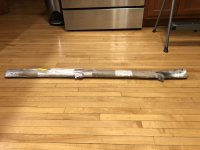
I received my replacement Parf sticks from Axminster. The package arrived fairly beat up. In the original order, the kit arrived in a tube inside a box, and was well protected. This time, it was just the tube, with no box.
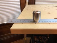
View attachment 1
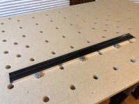
The Parf sticks were bent.
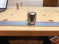
View attachment 2
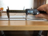
I was able to bend them back a bit, but they still didn't quite rest flat.
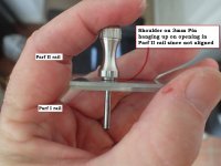
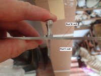
I'll call my first pair of Parf sticks A and B, and the second pair C and D. As I described earlier, the holes in A and B were slightly out of alignment. So were the holes in C and D. Luckily, the holes in A and C did line up, so I used that pair. (Of the six possible pairings, that was the only pair where the holes were in good alignment.)
Even though C was slightly bent, it didn't cause any problems with the hole layout.
This time, the hole layout went much more smoothly. In my previous attempt, I had some situations where I extended the top and bottom rows of 3mm holes to the right, but then could not get the Parf stick to line up with both the right-most top and bottom holes. This time, I didn't have that problem. There were a few situations where it was very tight and difficult to insert two distant pins through the Parf stick holes into the 3mm holes drilled in the MDF, but I found that I was able to push the pins sideways just a little, and since the MDF has a little give to it, this would slightly extend or shorten the distance between the pair of pins, allowing them to seat all the way in the Parf stick.
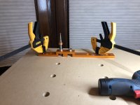
I found that inserting and removing the pins was in general very difficult because the fit in the holes was very tight. There's no way I could have inserted and removed them by hand without assistance. I ended up putting clamps on the pins (and leaving them on) so that there was a much larger handle to push, pull, and twist the pins. Here's a picture of the 20mm guide pinned to the worktop, where each pin is being held by a quick clamp.
View attachment 4
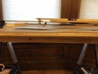
I added some holes that were offset by 48mm both horizontally and vertically, and I used the UJK chamfer cutter to chamfer the holes. Here is the end result. I think it turned out very nicely!
View attachment 3
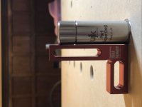
One thing that I was curious about was how close to perpendicular the 20mm holes would be. I drilled the 3mm holes as close to perpendicular as I could by hand, and the same for the 20mm holes. The guides help immensely, but still, most of the holes were slightly out of perpendicular. Here is a typical one; some were slightly better, some were slightly worse. (For this photo, I positioned the square from the direction that had the most error.)
View attachment 5
I also noticed that holes on one side of the the worktop tended to tilt one way, and holes on the other side tended to tilt the other way, probably because I have a systematic bias when drilling the holes (say, angling to the right), and I stood on opposite sides of the table to drill holes that were on opposite sides.
This could be an issue when the dogs are used to position the guide rail. Obviously, the thicker the stock being cut, the higher up the guide rail will be, and so the greater the cut error. I suspect that the small amount of error won't cause any real problems. The error could be reduced by using dog holes that are as far apart as possible -- this will reduce the error angle.
I also noticed that if I placed three dogs in one row, then pushed a good straightedge up against them, in most cases I could rock the straightedge a little bit (with the middle dog acting as the pivot point) if it was on one side of the dogs, but not the other. This indicates that the holes are slightly non-colinear. Again, I suspect that the amount of error is small enough that it won't cause any problems in real-world usage.
View attachment 6
I don't have access to a Festool MFT table, so I don't know how my worktop compares in terms of accuracy. At any rate, I am looking forward to getting some good use out of it!
View attachment 1
The Parf sticks were bent.
View attachment 2
I was able to bend them back a bit, but they still didn't quite rest flat.
I'll call my first pair of Parf sticks A and B, and the second pair C and D. As I described earlier, the holes in A and B were slightly out of alignment. So were the holes in C and D. Luckily, the holes in A and C did line up, so I used that pair. (Of the six possible pairings, that was the only pair where the holes were in good alignment.)
Even though C was slightly bent, it didn't cause any problems with the hole layout.
This time, the hole layout went much more smoothly. In my previous attempt, I had some situations where I extended the top and bottom rows of 3mm holes to the right, but then could not get the Parf stick to line up with both the right-most top and bottom holes. This time, I didn't have that problem. There were a few situations where it was very tight and difficult to insert two distant pins through the Parf stick holes into the 3mm holes drilled in the MDF, but I found that I was able to push the pins sideways just a little, and since the MDF has a little give to it, this would slightly extend or shorten the distance between the pair of pins, allowing them to seat all the way in the Parf stick.
I found that inserting and removing the pins was in general very difficult because the fit in the holes was very tight. There's no way I could have inserted and removed them by hand without assistance. I ended up putting clamps on the pins (and leaving them on) so that there was a much larger handle to push, pull, and twist the pins. Here's a picture of the 20mm guide pinned to the worktop, where each pin is being held by a quick clamp.
View attachment 4
I added some holes that were offset by 48mm both horizontally and vertically, and I used the UJK chamfer cutter to chamfer the holes. Here is the end result. I think it turned out very nicely!
View attachment 3
One thing that I was curious about was how close to perpendicular the 20mm holes would be. I drilled the 3mm holes as close to perpendicular as I could by hand, and the same for the 20mm holes. The guides help immensely, but still, most of the holes were slightly out of perpendicular. Here is a typical one; some were slightly better, some were slightly worse. (For this photo, I positioned the square from the direction that had the most error.)
View attachment 5
I also noticed that holes on one side of the the worktop tended to tilt one way, and holes on the other side tended to tilt the other way, probably because I have a systematic bias when drilling the holes (say, angling to the right), and I stood on opposite sides of the table to drill holes that were on opposite sides.
This could be an issue when the dogs are used to position the guide rail. Obviously, the thicker the stock being cut, the higher up the guide rail will be, and so the greater the cut error. I suspect that the small amount of error won't cause any real problems. The error could be reduced by using dog holes that are as far apart as possible -- this will reduce the error angle.
I also noticed that if I placed three dogs in one row, then pushed a good straightedge up against them, in most cases I could rock the straightedge a little bit (with the middle dog acting as the pivot point) if it was on one side of the dogs, but not the other. This indicates that the holes are slightly non-colinear. Again, I suspect that the amount of error is small enough that it won't cause any problems in real-world usage.
View attachment 6
I don't have access to a Festool MFT table, so I don't know how my worktop compares in terms of accuracy. At any rate, I am looking forward to getting some good use out of it!