Parf Guide mark 2 issues and questions

For what it's worth-

I bought a PGS, Mk2 about a month ago, and haven't put it to use yet.  But this video had me wondering- so I mocked it up on my MFT, and took a reading.

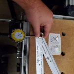
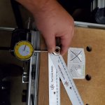
It's real.  It's about 0.010" of play.  You can tell just by feeling with your hand that the play is coming from the pin ends, not the drill guide.  The pins ARE dead tight in the MDF, and the drill guide joint has no tangible play, but the joint from the pin to the parf stick DOES. 

It really does FEEL like quite a bit of slop, but how much actual error is this?  Well, it's 0.010" at the end of a 39" run, so if my trig isn't too rusty, I'm getting 0.014 degree angle change (somebody please check this, I flunked out of college over a decade ago  [big grin]).  But that's the included angle- any actual error will be half this amount one way or the other.  So you're looking at 99.992% accuracy for your square cuts, if that's only if you do the WORST possible job when drilling your dog holes.  As Peter says, keeping the parf sticks in the center of the range will minimize this even further, and isn't hard to do by eye. 


Attachments

  • PGS 1.jpg
    PGS 1.jpg
    103.9 KB · Views: 541
  • PGS 2.jpg
    PGS 2.jpg
    102.8 KB · Views: 418
Followup to the above post---

I replaced the pins with tapered drywall screws to hold the far ends down, removing ALL play at that end.  The drill guide is now the weakest link, and the wiggle room dropped to 0.004".  Which I think is fantastic. 

Just by feel, the difference between 0.010" and 0.004" is pretty huge.  If it had been 0.004" right out of the box, I don't think I would have noticed it.  The ten-thou sticks out like a sore thumb. 
 
Hi all,

Just wondering if this is the most accurate way of extending the holes to the left and right of the bench? Where the two pins are on the top parf stick is where the last holes are.

Many thanks!

62de5fcba688d939576eeda8c40b0ff4.jpg

47302035811092b69ec0ae142729c29f.jpg
 
Hi [member=16995]AndrewG[/member]

I have just tried and failed to get a page of instructions to you with some diagrams - the FOG software is not the most friendly at times. I have even tried adding the instruction manual to this post with no luck. So...

Please follow this link:
https://www.axminstertools.com/ujk-technology-parf-guide-system-mkii-104779

Scroll down to and click on "Information Downloads" and then click on "Instruction Manual"

Peter
 
Thanks Peter- I actually had read the instructions but misinterpreted them.

I think I got the right set up now? 6-8-10 method

f67e5fb1e2568caaa067a50e9d7af827.jpg
 
Hi [member=16995]AndrewG[/member]

That does not look right. You should be creating a 6 - 8 -10 triangle. Maybe it is the angle of the camera - the left hand pin in the top ruler should be in the same column as the pin on the left on the angled ruler. Also, the number of 96 mm spaces should be 6 between those two pins.

Peter
 
That looks okay to me, although the wide angle perspective makes it difficult to be sure.

Taking perspective in mind it looks like the important pins are in the same column and it looks like there are 6 rows between those pins.
 
Peter Parfitt said:
Hi [member=16995]AndrewG[/member]

That does not look right. You should be creating a 6 - 8 -10 triangle. Maybe it is the angle of the camera - the left hand pin in the top ruler should be in the same column as the pin on the left on the angled ruler. Also, the number of 96 mm spaces should be 6 between those two pins.

Peter
Hi Peter,

Thanks for the reply. I’ve attached another photo which hopefully is clearer for you. I’m pretty confident it’s real but just want the tick of approval before I start drilling!

Many thanks.

1e0aebce3e60ff658e9e9d138ff23be8.jpg

b8a880bf74a006778c8c1d9c143dabaf.jpg

918a9c9935d2d8e296f8121efbbdcf83.jpg
 
Hi [member=16995]AndrewG[/member]

Perfect - many thanks for clarifying that as I would hate to give poor advice.

I recently gave a talk at a college here in the UK and I was asked to demo the PGS. I took along a folding MFT3 size bench that I made about 5 or 6 years ago. It had "gone missing" after a demo about 3 years ago and had come to rest in a stock room at Axminster. The 20 mm holes needed to be reamed out after such a long time without a dog going into them but it was still perfectly accurate.

My current tracksaw cutting station has lasted over 3 years and shows no sign of abuse. I think that reflects a slower work rate on my part as I used to produce a new one about every 2 years. What has helped is using a sheet of thin plastic over the top when I do glue-ups or apply Osmo.

Cheers.

Peter
 
Hi [member=16995]AndrewG[/member]

In your first picture you show 3 registered pins. I don't think that is possible unless the rulers are in the correct orientation.
 
Hi Peter, Frank, and tsmi243,

I'm about ready to order this kit, and find this "slop" issue a little concerning. Peter, you described it as having a neutral position and to "make sure the ruler(s) is not moved beyond that neutral rest position". However, tsmi243 describes it differently: "keeping the parf sticks in the center of the range will minimize this even further, and isn't hard to do by eye". This sounds more like you have to find the center of the range. Frank and tsmi243, did you experience feeling a neutral position that you had to move it from?

If this slop was cumulative then I could see it as being a problem. However, you would be able to check it by making sure the triangle could be pinned throughout the grid. That would ensure that your error wasn't cumulative and would be no greater than the original slop. I haven't seen any user complaints stating that their resulting grid wasn't accurate. Peter, you demonstrated with the 4 cut method that yours is very accurate. I wonder if others have actually tested theirs with similar results.

All of us have probably experienced clamping 2 boards together while gluing and seeing how easily they shift. That is because it is very hard to get the clamps perpendicular to the boards. When you tighten the clamps, they naturally want to move to that perpendicular position, and the slippery glue makes that shift easy. With slick guides on slick MDF I could see this as possible. I would suggest making a very thin pencil line against the rulers while they are in the neutral position prior to clamping. Then you could verify that your clamping technique doesn't cause a shift.
 
zak911 said:
tsmi243, did you experience feeling a neutral position that you had to move it from?

There's friction between the rules and the table top, as you said, so it doesn't completely spring into place.  And to clarify, the 1st rule moving under clamps isn't the issue.  It's the 2nd setup (the triangle) that determine the squareness.  The first hole you drill where the two sticks overlap is the most important one, and THAT hole is where I'm getting 0.010" of play in the pins. 

And again, 0.010" was the maximum travel I got, so it's really only 0.005" error, and only because I was TRYING to maximize the error.  If you feel around for center, even a minimum effort could net you a true error of 1 or 2 thou instead.  Across more than 36".  Whether that's worth worrying about, is up to you.
 
I ordered the Parf Guide Mk II as I plan to put together an MFT to use with my TS 55, however, my drill is a cordless 18v Makita. I think it’s the LXPH01.

Should I be worried about run out / drill accuracy / anything else? Or is this drill going to be fine to drill the holes? Thanks

 
The Drill will be fine. I made my mft  with a Hikoki cordless drill and the PARF guide.
 
Ampman117 said:
I ordered the Parf Guide Mk II as I plan to put together an MFT to use with my TS 55, however, my drill is a cordless 18v Makita. I think it’s the LXPH01.

Should I be worried about run out / drill accuracy / anything else? Or is this drill going to be fine to drill the holes? Thanks

The brand doesn’t matter but if you see the bit wobble when running get a different drill. Runout and jigs are not compatible.
 
Hi [member=79142]zak911[/member]

The system is really accurate and very easy to use as long as the instructions are followed and no short cuts taken. The PGS has had the most 5 start reviews of any product on the Axminster web site - take a look at those comments if you need convincing.

Cheers.

Peter
 
Hi Peter and tsmi243,

Thank you for the responses. I am convinced that the slop isn't an issue and I will be ordering soon.
 
Ok, so another question regarding the PG mk2. I’ve just drilled all the 3mm holes and everything lined up perfectly - very happy.

I’ve now started drilling the 20mm holes and at the stage where I need to use the 20mm locater dogs. I’ve noticed there is the tiniest bit of wobble when the dogs are in the parf jig registering with the existing 20mm holes drilled using the jig registering with the pins only.

The holes are tight in the top with no movement, they’re not the issue. The issue is when they’re in the jig through the holes in the top.

I even tried using it with the super dogs with the larger collar - same issue. As you can see in the photo the dogs do fit in the jig, but if I move it front to back there is a very small amount of movement.

So it’s got to be the jig I assume? Does anyone elses jig have the smallest amount of play when the locater dogs are in the jig when drilling out the 20mm holes?

Thanks once again

Cheers
19a52b27b60bf9c8881bcd5408b6e7d7.jpg

2840bef9906e6302423f22ce039236bb.jpg
 
I know this is totally daft (please don't laugh too hard [embarassed] ), but I am still thinking of a way to modify this system to make 3/4" or 19 mm holes.  [huh]

I don't own any 20 mm stuff and am not planning to buy any either. I get by with 19 mm holes just fine. I have a serious collection of clamps and jigs to go with them too. However, there are some applications where an exactly spaced/placed grid of holes might be useful. Even in my case.

Any ideas on how to approach this best? I guess I'd need to replace the bearings and the dogs. Anything else?

 
Back
Top