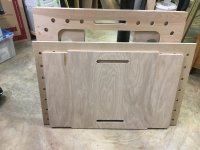
I was about to make a somewhat modified version of Ron Paulk's workbench using plans that I had purchased from him, with the modifications involving making it shorter so that it would fit into my SUV. I had already created templates to pattern rout the sawhorses and the spacers, and I had already purchased the plywood, when I saw a post on here that reminded me of a folding workbench that I had built about 35 years ago, as well as plans that were published in Wood Magazine a few years ago for a folding assembly table. While the OP indicated that he would not be selling plans, at least one forum member properly noted that this being a woodworkers' site, 90 percent of the members could probably create something similar without additional information. As I had a LOT of "scrap" plywood and MDF in various sizes and shapes already cluttering up my shop (which SEVERELY required a cleaning), I measured what I had, and decided to redesign the folding workbench that was posted. In addition, several years ago I had built a "Router Table" top to accommodate an Incra LS-17 Positioner along with an Incra "Super Fence" with integrated dust collection, but I never designed or built any form of enclosure for it, so the top was merely attached to a frame that I had put together. As I wanted to take advantage of the already-built Router table top, and as I did not like the OP's approach to attaching an MFT-style top to the folding bench, as it required forming mortice and tenon joints that I felt were overly size-sensitive, and not conducive to replacement tops (MFT or Router types), I redesigned the attachments, and came up with the following that was made exclusively from scrap that I had cluttering up my shop:
You are using an out of date browser. It may not display this or other websites correctly.
You should upgrade or use an alternative browser.
You should upgrade or use an alternative browser.
Portable, Folding Workbench With MFT, Router Table, and Other Tops
- Thread starter sandy
- Start date
[member=66616]Jurgen W[/member] ...
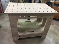
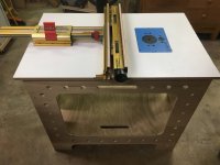
As you will note, the table posted in the YouTube video uses a "mortice and tenon" attachment to connect the table top to its sides. The use of that method requires very accurate cuts on both the top and on the sides of the table, whereas I used a different method for attaching the top in my version. Due to the different method that I employed, I was able to (within a very few minutes) remove the MFT style top and replace it with a Router Table top that I had designed and built about 11 years ago.
As I indicated, other specialized tops can be readily made and installed on my version without need for the precise mortice and tenon cuts shown in the YouTube version.
[member=3194]sandy[/member]
Thank you for your reply, and I didn’t want to imply anything, in fact, want to complement you on your different way tackling this idea and make it more useful to attach another top on the base..... I am in the process making one my own, and will also make another modification on it for my purpose: using it as an assembly table and outfeed table for my job site Sawstop. If I could ask, would you have a picture that kind of shows your technique of connecting the top with the base? Or perhaps you had plans for the base that you are willing to share/sell?
My main question I had under the video (perhaps you might have missed) did you use regular plywood 3/4, or is the base lightweight plywood that is often used in campers and boats?
[member=66616]Jurgen W[/member]
I haven't been on this thread in quite a while, so I apologize for having missed your question about the material that I used. It is actually 1/2" plywood, which makes a surprisingly sturdy table once the bottom insert and top are installed (see my response to Bob D. below). In fact, I weigh 225, and it's quite stable when I stand on it once it's fully assembled. Note, though, that the screws that came with the piano hinges that I purchased are actually about 5/8" long, so after I assembled the bench and screwed the hinges on it was necessary for me to use my Dremel to grind down the points of the screws, whereby you can see small "burn" marks which occurred when the Dremel bit bottomed out on the plywood.
[member=60461]Bob D.[/member]
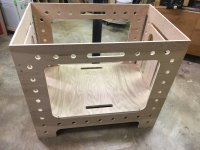
As I said, in an earlier post, the problem that I saw with the table in the YouTube post was that it required very accurate mortice cuts through the top, while requiring similarly accurate tenon cuts on the long sides. Also, to keep the top level, the length of the tenons had to exactly match the thickness of the top. As the ends are each made of two pieces with hinges that allow the two piece ends to fold inward when the base is collapsed, the bottom piece adds a lot of structure to force each of the two piece ends outward, thereby strengthening the base, while the mortice/tenon attachment of the top to the long sides in the YouTube video only urged the two ends to stay "opened" when the top was in place. My alternate, more secure, and much simpler, approach was to cut the sides with straight tops, i.e., without tenons. Instead, I took a piece of aluminum angle (1" x 1") , and I cut it into eight pieces (for each top), each of which was about 1 1/2" long. I drilled a pair of screw holes into each of the angle pieces to allow them to be screwed into the underside of the top. I then opened the base fully, placed the top on top of the base, and placed two of the angles on the underside of the top adjacent to each of the side pieces using double sided tape. Once those four were screwed into place, I used the other four angles under the ends of the top to push the ends out (one angle on the inside of each of the four end pieces), thereby forcing the end hinges to stay fully open. Once the angles are screwed into place under each of the tops, the tops need merely be placed on the base while holding the end pieces fully open, and the aluminum angles hold everything in place, forcing (rather than urging) the ends to remain fully open. Unlike the YouTube version, mine requires no measuring, it "self-aligns", and there is no issue with the tenons being too low or too proud of the top, which retains a totally flat upper surface. That was especially important when I adapted the Router Table top to the base.
If there is sufficient interest in plans, I could, certainly, put a set together, so, guys, let me know if there's interest.
I haven't been on this thread in quite a while, so I apologize for having missed your question about the material that I used. It is actually 1/2" plywood, which makes a surprisingly sturdy table once the bottom insert and top are installed (see my response to Bob D. below). In fact, I weigh 225, and it's quite stable when I stand on it once it's fully assembled. Note, though, that the screws that came with the piano hinges that I purchased are actually about 5/8" long, so after I assembled the bench and screwed the hinges on it was necessary for me to use my Dremel to grind down the points of the screws, whereby you can see small "burn" marks which occurred when the Dremel bit bottomed out on the plywood.
[member=60461]Bob D.[/member]
As I said, in an earlier post, the problem that I saw with the table in the YouTube post was that it required very accurate mortice cuts through the top, while requiring similarly accurate tenon cuts on the long sides. Also, to keep the top level, the length of the tenons had to exactly match the thickness of the top. As the ends are each made of two pieces with hinges that allow the two piece ends to fold inward when the base is collapsed, the bottom piece adds a lot of structure to force each of the two piece ends outward, thereby strengthening the base, while the mortice/tenon attachment of the top to the long sides in the YouTube video only urged the two ends to stay "opened" when the top was in place. My alternate, more secure, and much simpler, approach was to cut the sides with straight tops, i.e., without tenons. Instead, I took a piece of aluminum angle (1" x 1") , and I cut it into eight pieces (for each top), each of which was about 1 1/2" long. I drilled a pair of screw holes into each of the angle pieces to allow them to be screwed into the underside of the top. I then opened the base fully, placed the top on top of the base, and placed two of the angles on the underside of the top adjacent to each of the side pieces using double sided tape. Once those four were screwed into place, I used the other four angles under the ends of the top to push the ends out (one angle on the inside of each of the four end pieces), thereby forcing the end hinges to stay fully open. Once the angles are screwed into place under each of the tops, the tops need merely be placed on the base while holding the end pieces fully open, and the aluminum angles hold everything in place, forcing (rather than urging) the ends to remain fully open. Unlike the YouTube version, mine requires no measuring, it "self-aligns", and there is no issue with the tenons being too low or too proud of the top, which retains a totally flat upper surface. That was especially important when I adapted the Router Table top to the base.
If there is sufficient interest in plans, I could, certainly, put a set together, so, guys, let me know if there's interest.
Sorry to be asking so late but I've only just seen the [member=3194]sandy[/member] explanation of your angle for location of the top. I'm not quite clear on the locations of the angle pieces. If you have time a picture would help tremendously.
Thanks
Thanks
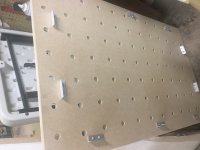
sandy said:Here ya go...
Perfect, thanks.
The location of the end fittings was clear from the written explanation the side ones not so much, so that picture makes it obvious.
In looking at my own photo, my earlier description was a bit inaccurate, as I actually used three angles along each side, for a total of six along the sides, rather than four. I used two along each end, so that there was one on each of the four end panels.
Note that while I used aluminum angles, you could also use wood blocks, as the important things are only that (a) the inside distance between the outside edges of the angles/blocks be the same as the distances between the sides/ends; (b) with respect to the ends, it's best if the ends/blocks are relatively close to the middle of the top to insure that the hinges are fully opened when the top is in place; and (c) the dimensions of the sides/ends should be such that the tops of the sides/ends will not interfere with the holes in the top. Note that the angles/blocks can be placed between the holes, as shown, so that they don't interfere with any clamps, etc. inserted into the holes once the top is in place.
As you can see, this approach, unlike the ones shown by Coach.carpenter and/or fyme, is very simple, requires no special cuts in either the sides/ends and/or top, and can be readily adapted to existing tops, like the router table that I have had for several years. Consequently, if you are going to a job site, or you need space in a small shop, you need only have one set of sides/ends and one bottom panel, while you can have a number of different, interchangeable, tops, i.e., MFT, sacrificial top for breaking down sheet goods, router table, Bessey clamp table, Kreg-type clamp table (with T-track), downdraft sanding, etc., basically an endless variety of tops with only a single base. Alternatively, you can have multiple bases that can be stored (folded up) in very little shop/vehicle space. I should also add that if you have an idea for a new type of bench you can easily prototype it by making only the top which can then be placed in position on the base. By way of example, I have built a number of rocking horses for my grandchildren, and I keep thinking that it would be great to have a "sky hook" to hold the body up, while trying to arrange the legs and rockers in position for assembly.
If the photos and explanations were not adequate, I am willing to prepare plans, which I will make available for a nominal price. Also, I have a Shaper Origin, so I am thinking of creating a set of CNC files for it to make either entire units or router templates.
Sandy
Similar threads
- Replies
- 4
- Views
- 607
- Replies
- 20
- Views
- 1K
- Replies
- 14
- Views
- 1K