Proper use of LR32 Stops

JBird

Member
Joined
Feb 16, 2012
Messages
116
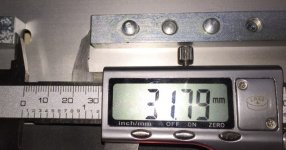
Just finished my first LR32 project and I ran in to some difficulty using the stops as described in the manual. The main difficulty was that my stops are not spaced an even 32 mm apart. See my photo of the caliper showing 31.79mm.

[attachimg=1]

If they had been 0.21 too big then I would have been close enough for my work. But since they were too small they would not fit on my already precisely cut workpieces. Rather than trim a hair off all my pieces I simply resorted to using one stop registered off the same end of the work after I flipped the rail. The results were fine but there is an added inconvenience in having to remove the stop and reposition it to the other side of the rail after each flip. I would really rather use the stop as intended.

Has anyone else found that their stops are not a more accurate 32 mm apart? Seems like I have a few choices for future projects:

[list type=decimal]
[*]Cut all my pieces 0.21 too short. But none of my measuring devices have better than 1 mm increments.

[*]Mill some material off these stops to make them closer to 32 mm, and maybe just a hair bigger to allow for imprecision in my cuts.

[*]Use only 1 stop at a time and accept the inconvenience of removing and flipping the stop.

[/list]

From what I have read a lot of you are using only 1 stop, but that seemed to be because your work pieces were not in increments of 32. Is anyone else forced to do that due to the imprecision of the stops?

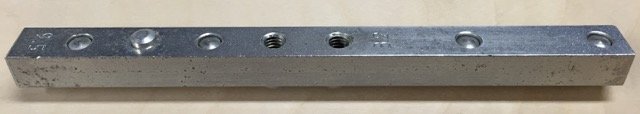
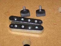
While examining the stops to troubleshoot this problem I observed that when used on the 32 mm position there is only 1 pin that engages the rail.

[attachimg=2]
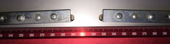
Due to the play in the thumbscrew this allows for quite a bit of error in their alignment and requires extra effort to make them parallel. See photo for example of how bad it can be.

[attachimg=3]

It seems odd that on the top side of the rail there are channels that perfectly fit the stops and would keep them parallel. But no such channel exists on the bottom side where they are needed.

The 16 mm side engages at least 2 pins at all times and so the placement does't involve so much play.

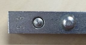
I have watched many of the LR32 tutorials and my stops are different from every example I have seen. Mine have an additional position for 9.5 mm.

[attachimg=4]

Does anyone know what the 9.5 position would be used for? Do the older style stops without the 9.5mm have two pins for the 32 mm position?

Thanks for any insight or tips you can provide.
 

Attachments

  • precision.jpg
    precision.jpg
    76.7 KB · Views: 1,808
  • pins.jpg
    pins.jpg
    26 KB · Views: 1,754
  • alignment.jpg
    alignment.jpg
    43.2 KB · Views: 1,750
  • ninepointfive.jpg
    ninepointfive.jpg
    69.8 KB · Views: 1,801
The old stops weren't able to be used as a spacer to aid in accurately joining two FS 1400/2-LR (holey) rails. The new stops allow that and also introduce the 9.5mm measurement alongside the 16mm and 32mm ones.

[attachimg=1]

[Stole Brice's photo from http://festoolownersgroup.com/festool-how-to/festool-lr32-how-to/]


I've seen people on this forum modify the stops to suit particular systems (grinding off 3mm for a 35mm measurement on the KISS II springs to mind) so if you want absolute accuracy and your stops aren't spot-on, don't be afraid to do that.

With regard to the 9.5mm stop, it comes from half the height of 19mm material.

See http://www.benchmark.20m.com/tools/Festool/32mm/festool_32mmholes.html and http://davelers.com/32mm/Styles/Inset_Flush/ for some great 32mm system information and details on where you might make use of the mysterious 9.5mm measurement.
 

Attachments

  • 1146_25_03_07_5_01_35.jpg
    1146_25_03_07_5_01_35.jpg
    44 KB · Views: 1,762
Interesting to see how the older stops are rounded on the ends which I expect makes them more forgiving if they are not setup parallel.  Thanks for those links.
 
Willy, maybe you know.  I admit that I haven't used the LR-32 since class and that one was before they added the 9.5 feature, but don't some of the knock down fittings also start that low.  Just trying to clear out by brain here.

Congrats on the demo!  I might try and make it up.

Peter
 
Peter Halle said:
Willy, maybe you know.  I admit that I haven't used the LR-32 since class and that one was before they added the 9.5 feature, but don't some of the knock down fittings also start that low.  Just trying to clear out by brain here.

Congrats on the demo!  I might try and make it up.

Peter

Some but not all of the manufacturers adopted the 9.5mm first hole setting back in the 40s.  Ikea is just one that comes to mind.  The KD fitting spacing uses the standard that the manufacturer selects.  They all seem to fit the paradigm. 

If you can be there for the demo, I'd be tickled silly. 

[smile]

 
Sparktrician said:
Peter Halle said:
Willy, maybe you know.  I admit that I haven't used the LR-32 since class and that one was before they added the 9.5 feature, but don't some of the knock down fittings also start that low.  Just trying to clear out by brain here.

Congrats on the demo!  I might try and make it up.

Peter

Some but not all of the manufacturers adopted the 9.5mm first hole setting back in the 40s.  Ikea is just one that comes to mind.  The KD fitting spacing uses the standard that the manufacturer selects.  They all seem to fit the paradigm. 

Hafele, Rafix etc. knock down fittings use 9.5mm first hole setting with 19mm panels.
The introduction of the 9.5mm spacer has made it easier for me to center the Hafele hardware on my 19mm panels.
Tim
 
Unless all the error is on one stop you don't need to only use one stop.  Just space the two stops with an extra 32mm space.  For example, if you have a 768mm panel space the stops for 800mm.
 
Brice Burrell said:
Unless all the error is on one stop you don't need to only use one stop.  Just space the two stops with an extra 32mm space.  For example, if you have a 768mm panel space the stops for 800mm.

That would save the trouble of switching the stop over. One disadvantage to this is that if you have marked the rail with ballanced plunge locations then they will all be off by one when you slide against the opposite stop.
 
I got the LR 32 system. I never had a problem with it. used the stop 16 side up, place it in between the 2 rails, ensure I can see the = on the stop, tighten the connectors put the stop on the end 16 up and out and call it good.

to easy
 
JBird said:
But since they were too small they would not fit on my already precisely cut workpieces.

You are talking about less than a quarter of a millimeter.

I am curious, what are you making that requires that level of accuracy?

I can't/don't work to tolerances higher than .5 mm.
Most glue ups will cancel out tolerances any closer than that.

Tim
 
Tim Raleigh said:
You are talking about less than a quarter of a millimeter.

I am curious, what are you making that requires that level of accuracy?

I can't/don't work to tolerances higher than .5 mm.

I don't require a high level of accuracy and i'm delighted to achieve +/- .25 (.5mm overall). If the stops had been 32.25 mm apart then they would have worked great for my cut and for my desired precision. But since they are undersized by -.21 that means I would have to target my cuts at 31.54 +/- .25 in order to insure they will fit between the stops.  Even if the stops had been exactly 32, I would still have to target my cuts at 31.75 to ensure my work would fit between the stop with my +/- .25mm cut tollerence.

So it would seem like for people like you and I who try for .5 mm tolerance the stops need to be 32.25 apart. I have to make some repairs to my milling machine but when I'm done I think I'll trim the stops to 32.25 and i'll also put a radius(extending from the nearest pin) on the ends to ensure they remain accurate, and slide easy along the work, if misalligned.
 
JBird said:
Tim Raleigh said:
You are talking about less than a quarter of a millimeter.

I am curious, what are you making that requires that level of accuracy?

I can't/don't work to tolerances higher than .5 mm.

I don't require a high level of accuracy and i'm delighted to achieve +/- .25 (.5mm overall). If the stops had been 32.25 mm apart then they would have worked great for my cut and for my desired precision. But since they are undersized by -.21 that means I would have to target my cuts at 31.54 +/- .25 in order to insure they will fit between the stops.  Even if the stops had been exactly 32, I would still have to target my cuts at 31.75 to ensure my work would fit between the stop with my +/- .25mm cut tollerence.

Move the stops back to the next 32mm position on the rail (so you can fit your panel in between the stops, and then move the rail with the stop attached to the appropriate edge of the panel (top or bottom) vs. cutting the material shorter to fit the spacing.
Tim
 
Tim Raleigh said:
Move the stops back to the next 32mm position on the rail (so you can fit your panel in between the stops, and then move the rail with the stop attached to the appropriate edge of the panel (top or bottom) vs. cutting the material shorter to fit the spacing.

I expect that is closer to the way most people use it. A second look at the the manual shows installing the stops at the very end of the rail on both sides without any attempt to size them for the board. They are apparently not designed to be used the way I want to use them.

There is a technique for marking the rail with your plunge locations which you have probably seen if you have watched many LR32 videos. If the stops are sized for the board then then markings on the rail will be correct in both orientations (assuming the hole locations are balanced). But if the stops are not sized to the board then the markings will be offset after flipping the rail. At that point it would be way faster to just move the stop then to offset all the markings on the rail.

I see now that i was simply trying squeeze more efficiency out of the LR32 then it was designed to deliver.
 
Sparktrician said:
If you cut your material in multiples of 32mm, you'll be able to make consistent spacings using the end stops set to the length of your material.

The OP's stops are .21mm smaller than 32mm so it's a bit of a squeeze if he is using multiples of 32mm, so hence his original question.

I have forced dovetails that were tighter than .21mm so I don't think it's probably doable.
Tim

 
JBird said:
But if the stops are not sized to the board then the markings will be offset after flipping the rail. At that point it would be way faster to just move the stop then to offset all the markings on the rail.

Trust me it's not.
Even on long, >1920mm panels but particularly on short panels where it's easier to turn the panel and leave the rail in place. Marking a bottom and top in those instances makes referencing and milling from the same side easier than moving the stop.
Tim
Tim
 
I just picked up the LR32 system and I'm having the same issue with my stops being to snug. I cut all of the side panels for my closet system to 1120mm, but the rail doesn't fit. I wish I would have realized this before making all my cuts. I found this video while searching for an answer to my problem. I really don't want to cut all the pieces again, so this should work for this round..

 
Back
Top