sawdust-samurai said:
As to my actual cut order, it was Cyan/Lt Blue followed by Green. I then cut both pink and black with the TSO square referenced off the Cyan line.
Ok, this may be part of it. It took me a second to wrap my head around, since my track square only cuts one direction, that was my thinking. However, since you have a TSO, it could be done that way.
Plus, we are still not sure of the straightness of this rail? Moving/repositioning the square on the rail
and cutting in opposite directions, introduces a lot of variables.
Assuming your rail and square can make a 90 degree cut, there is no reason that you couldn't reference the opposite sides, since they are "known" to be parallel.
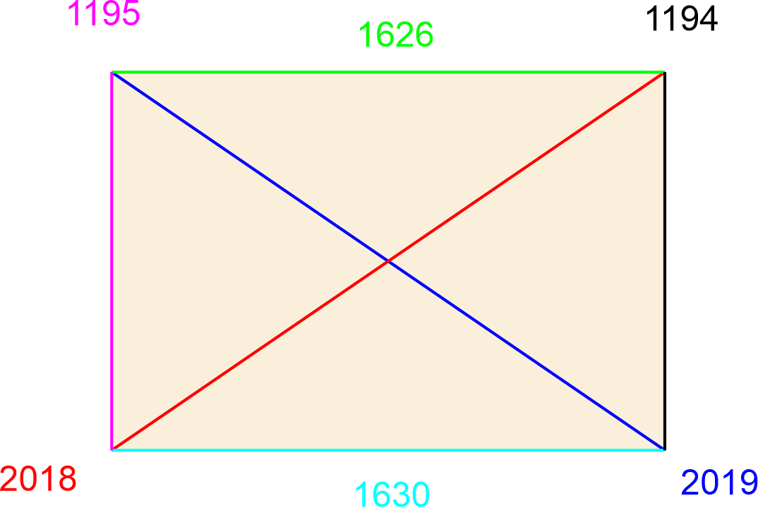
Meaning, if the cyan/black cut is square, you take the same track/rail square around and cut the green/purple.
At that point, the worst you can have is a parallelogram, every side will be equal, only the diagonals will be off. Then you know where you are....you are not cutting square. Easier to diagnose.
")