niallsmart
Member
- Joined
- Oct 29, 2021
- Messages
- 19
Hey folks,
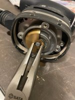
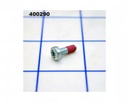
I'm attempting a repair on an out of warranty RTS400. This is not my first repair rodeo, but I've been stymied by removal of the brass counter weight (aka "cam"). From the parts diagram, it appears to be secured to the spindle with an M4 bolt (part #32).
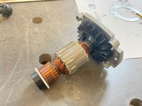
There are two indentations in the cam, which presumably receive a special tool used to hold it still while removing the screw. I'm using a large needle nose pliers for this purpose. However when I turn the screw counter-clockwise, the armature/shaft actually turns as well, so the screw doesn't actually loosen. I am having to apply a large turning force for the screw head to move, so my guess is that the red thread locker applied at the factory is stronger than the friction between the brass cam and the spindle.
Would appreciate any tips from folks who have experience disassembling this tool. Perhaps I'm going about this the wrong way entirely, or there's some way of locking the spindle. I've attached two photos which might be helpful...
Thanks,
Niall
I'm attempting a repair on an out of warranty RTS400. This is not my first repair rodeo, but I've been stymied by removal of the brass counter weight (aka "cam"). From the parts diagram, it appears to be secured to the spindle with an M4 bolt (part #32).
There are two indentations in the cam, which presumably receive a special tool used to hold it still while removing the screw. I'm using a large needle nose pliers for this purpose. However when I turn the screw counter-clockwise, the armature/shaft actually turns as well, so the screw doesn't actually loosen. I am having to apply a large turning force for the screw head to move, so my guess is that the red thread locker applied at the factory is stronger than the friction between the brass cam and the spindle.
Would appreciate any tips from folks who have experience disassembling this tool. Perhaps I'm going about this the wrong way entirely, or there's some way of locking the spindle. I've attached two photos which might be helpful...
Thanks,
Niall