Rexroth router table with OF2200 (aluminum profiles like 80/20)

sgryd

Member
Joined
May 14, 2007
Messages
362
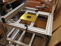
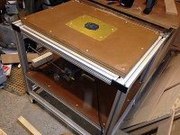
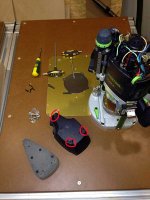
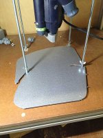
Efter many moons I revisited my Rexroth router table extension for my beloved Rexroth "MFT". Today the parts arrived and I think it's going to be really nice.

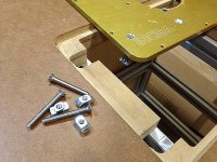
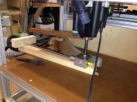
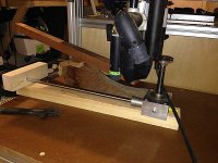
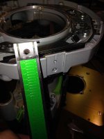
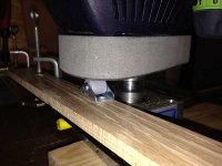
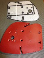
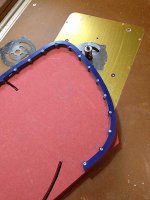
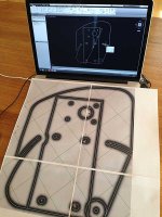
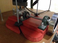
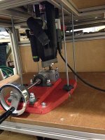
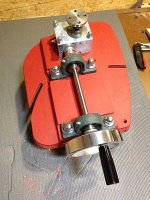
As the profiles already gave me two parallel tracks, I thought I'd build some kind of sled for it. Rexroth has bearing wheels that fit in the tracks. I think this sled can be used for very fast and accurate finger joints and half-in-half grids for box internals.

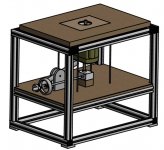
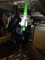
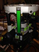
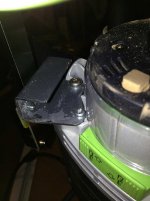
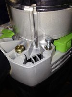
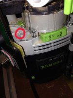
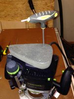
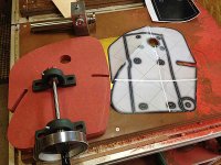
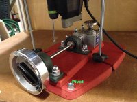
The router (OF 2200) will be moved up/down with a screw jack. For speedy bit change I'll also build a lever for speed lifting. I'll report back when the table is done. Thank you all 80/20 enthusiasts on the FOG for getting me going on this. Aluminum profiles are really addictive. It's almost as those green tools =)

[attachthumb=#]

[attachthumb=#]

//Michael
 

Attachments

  • RouterTable01.jpg
    RouterTable01.jpg
    73.5 KB · Views: 20,019
  • RouterTable02.jpg
    RouterTable02.jpg
    56.8 KB · Views: 4,024
I'm not sure if I understand the question. The sled will not be fastened, but roll over the router bit just like a cross cut sled on a table saw. The sled will probably get a number of jigs/stops/nuts/bolts for various projects. The beauty of Rexroth and 80/20 is that it's so easy to attach whatever you want. I'll probably attach an MDF board at the face of the sled for zero clearance, and possibly some kind of clamps.

I have an Incra LS as router fence. The LS will be attached on the other table.

Did I answer the question?

//Michael
 
Wow! That fence really spins the imagination. I could definitely implement some of the ideas from the JMPV2.

I might even think about implementing the bottom plate. The OF2200 has quite big plunge depth, so I suppose I'll have space for a bottom plate. Seems great to be able to clamp the work down as well. This will not be top priority in the project. I'll post back if/when some of this gets implemented.

//Michael
 
The project moves slowly forward. Thought I'd post some pictures. Please chime in if you have idéas to share about  the build. Next up is an attempt to mount my Wixey digital readout on the OF2200. Anyone tried this?

I ordered a blank router plate from Incra because I really like the magna lock system. What I don't like is the trouble I've had to level the plate in various other router tables, so I drilled some new holes in the plate to be able to anchor it solidly in the aluminum profile.
[attachthumb=#]

This is a prototype of the screw jack mounting. The axel will sit in a bearing block instead of a wood block.
[attachthumb=#]

I want to be able to disengage the screw jack for speedier work with a lever. Therefore the mounting plate for the jack will be able to slide so the jack can be pushed away from the router.
[attachthumb=#]

Overview image.
[attachthumb=#]

//Michael
 

Attachments

  • RouterTable03.jpg
    RouterTable03.jpg
    76.9 KB · Views: 3,504
  • RouterTable04.jpg
    RouterTable04.jpg
    71.5 KB · Views: 1,904
  • RouterTable05.jpg
    RouterTable05.jpg
    55.5 KB · Views: 1,556
  • RouterTable06.jpg
    RouterTable06.jpg
    76.2 KB · Views: 4,266
I'll keep updating this thread for those interested. I've after some work managed to fit the Wixey on the OF2200. They are not made for each other, but I'm happy with the solution.

The scale fits perfectly in the slot at the base of the router. I thought, "easy. I'll just make the hole in the scale a bit bigger to fit an M6". 6mm is a tiny hole. I have a drill press and good drill bits. I even tried to step drilling. Could't even go from 4 mm to 4,5 mm. Darn thats a hard scale.
[attachthumb=#]

I ended up drilling a new hole in the base instead. First I had to clean the back of the hole by filing down a small aluminum part.
[attachthumb=#]

I needed a solid way to fasten the sliding part of the Wixey. Found a small hole (4 mm) which carefully tapped to M5. Couldn't get a 4,2 mm drill bit in place, but the 4mm hole took the tap gracefully. The screws holding the plastic part of the router are recessed in an hole. I put a washer (actually a drilled nut) in the recess to get the screw level with the surface.
[attachthumb=#]

The two screws that will hold the Wixey
[attachthumb=#]

I made a holding plate out of some scrap metal.
[attachthumb=#]

Fitting nicely and feels solid.
[attachthumb=#]

Router is back in the table.
[attachthumb=#]

//Michael
 

Attachments

  • RouterTable13.jpg
    RouterTable13.jpg
    55.6 KB · Views: 960
  • RouterTable12.jpg
    RouterTable12.jpg
    61.2 KB · Views: 998
  • RouterTable11.jpg
    RouterTable11.jpg
    55.7 KB · Views: 612
  • RouterTable10.jpg
    RouterTable10.jpg
    68.6 KB · Views: 669
  • RouterTable09.jpg
    RouterTable09.jpg
    69.8 KB · Views: 924
  • RouterTable08.jpg
    RouterTable08.jpg
    84.7 KB · Views: 775
  • RouterTable07.jpg
    RouterTable07.jpg
    59.5 KB · Views: 974
Nice setup. Where did you find that screw jack?

Best, Karel
 
A small update on the project.

I needed a flat sturdy surface to push the router with the screw jack as well as with the pivot bar. The pivot bar is essentially moving as a radius, hence a chosen point on the bar will not be fixed relative to the router when raising the bar. I will put a wheel on the bar which can travel over the flat surface I have created. The wheel travels almost an inch while rising the router with the pivot.

The OF 2200 has three "pillows" on the top which are perfectly level. I figured I could use those as support for my flat surface. But I also wanted to take advantage of the curved surface on the top of the router as it turned out that this surface is very well supported from inside of the router.

I used a triangular (kind of) block of 30mm MDF. I bored out recesses for the three pillows to rest in and then I carved a concave surface to match the convex surface of the router.

[attachthumb=#]

[attachthumb=#]

I screwed the MDF block from inside of the router.
[attachthumb=#]

I screwed back the top of the router through the tool holes I made in the block.
[attachthumb=#]

Here is a mock-up of the pivoting bar with the wheel. It works really well.
[attachthumb=#]


Attachments

  • RouterTable18.jpg
    RouterTable18.jpg
    42.2 KB · Views: 969
  • RouterTable17.jpg
    RouterTable17.jpg
    45.9 KB · Views: 755
  • RouterTable16.jpg
    RouterTable16.jpg
    65.9 KB · Views: 671
  • RouterTable15.jpg
    RouterTable15.jpg
    64.9 KB · Views: 721
  • RouterTable14.jpg
    RouterTable14.jpg
    44.3 KB · Views: 1,090
At last I found time to finish the screw jack mounting. Next up is the speed-lift, i.e. a lever to lift the router to top position when changing bits. I don't want to wind it up with the jack since it only moves 2 mm per revolution.

[attachimg=#]

The jack in "engaged" position.
[attachthumb=#]

The mounting plate pivots around a nut. The disengaged position will come in handy if I have the jack screwed all the way up and I need to clear the table. Instead of winding it all the way down I'l disengage the jack and lover the router with the speed lever.
[attachthumb=#]

It actually got a lot more work than I had anticipated. Drew a cad drawing to get the pivot correctly.
[attachthumb=#]

Protoype to check the pivoting.
[attachthumb=#]

Routing the outer shape
[attachthumb=#]

Bottom plate routed
[attachthumb=#]

The under side of the bottom plate after making all the recesses needed for the nuts.
[attachthumb=#]

Top and bottom plate glued together
[attachthumb=#]

Test assembly
[attachthumb=#]


Attachments

  • jack09.jpg
    jack09.jpg
    69.8 KB · Views: 549
  • jack08.jpg
    jack08.jpg
    57.8 KB · Views: 576
  • jack07.jpg
    jack07.jpg
    67.1 KB · Views: 691
  • jack06.jpg
    jack06.jpg
    46.8 KB · Views: 606
  • jack05.jpg
    jack05.jpg
    56.6 KB · Views: 639
  • jack04.jpg
    jack04.jpg
    55.8 KB · Views: 792
  • jack03.jpg
    jack03.jpg
    52.6 KB · Views: 1,032
  • jack02.jpg
    jack02.jpg
    54.8 KB · Views: 1,097
  • jack01.jpg
    jack01.jpg
    61.3 KB · Views: 4,219
  • jack10.jpg
    jack10.jpg
    79.6 KB · Views: 985
It was this project that inspired my own attempt;


This is hanging off a Hammer K3 slider with Incra rails that supports an LS positioner with a router lift in the centre to take advantage of the fence for routing and cutting. Clearly early days and I won't hijack your thread with my own project, I'll start a new thread, but thought I would just jump in to say this Bosch Rexroth extrusion is the mutts nuts and I'll be watching this with keen interest.

Superb work and inspiration Michael  [smile]
 
There is a very simple way ... Bessey KT5-1CP

bessey_lift_s.jpg
 
Amazing stuff guys. I've just scored 17m of 40x40 profile and 4m of 80x40 so looking for a project. Only trouble is that the 40mm stuff only has channels on 2 sides. Some on opposing faces and some at 90 deg to each other. But I should manage to get it to work in.

Where in the uk can I get those angles and nuts?
 
Bigchasbroon said:
Amazing stuff guys. I've just scored 17m of 40x40 profile and 4m of 80x40 so looking for a project. Only trouble is that the 40mm stuff only has channels on 2 sides. Some on opposing faces and some at 90 deg to each other. But I should manage to get it to work in.

Where in the uk can I get those angles and nuts?

I've used these a fair bit, delivery charge is quite high for the heavy stuff but overall best price I could find for Bosch Rexroth and they are a good company to deal with - highly recommend them;

http://www.aluminium-profile.co.uk/
 
Bigchasbroon said:
Amazing stuff guys. I've just scored 17m of 40x40 profile and 4m of 80x40 so looking for a project. Only trouble is that the 40mm stuff only has channels on 2 sides. Some on opposing faces and some at 90 deg to each other. But I should manage to get it to work in.

Where in the uk can I get those angles and nuts?

Also try  Motedis.co.uk .  Similar stuff just cheaper.
Dave
 
Back
Top