Sketchup hole grid work question

mattbyington

Member
Joined
Mar 11, 2018
Messages
797
Hey guys,

Sorry for the stupid question. I am embarking on the process of converting my 3 MFT/3s to have storage underneath.

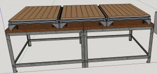
I am going with 2x Rockler adjustable shop stands under (48" square).

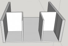
I'm working on designing it in SketchUp. I'm designing space for Sys a-z drawers now.

My stupid question is really about hole placement. I posted this on Facebook too, let me copy it from there:

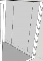
"Hey team! Hopefully a quick and stupid question. I'm designing a workbench in Sketchup that will 3 Festool MFT tables will sit on. I know I could build my own, but I already have the 3 MFTs so I want to use them. Anyways, the table will be supported by 2x Rockler Shop Stands that come in various size stretchers. I will have 2x 48" square ones side by side. Question is - I've been laying out the "innards" (where I'll mount drawers for the Festool sustainers etc) - what's the best way in Sketchup to "mark" a hole location? I started off just drawing a circle with a radius of say 3 or 3mm, and extruding it down (like a hole). Problem is, when I would go to look at these plans, it wouldn't be entirely obvious where the exact center of the hole should be drilled. It's almost like you just want a pin point saying drill the hole here, rather than the hole itself. Sorry if this is a totally stupid question! I'm not great at Sketch up."

Another add-on - how would I "copy" this gridwork/layout to the other wall (the left hand side that needs the exact same hole spacing).

Sorry if it's a dumb question and thank you so much in advance!

Matt

[attachimg=1][attachimg=2][attachimg=3]
 

Attachments

  • Untitled.jpeg
    Untitled.jpeg
    535.4 KB · Views: 1,693
  • Untitled2.jpeg
    Untitled2.jpeg
    226 KB · Views: 1,660
  • Untitled3.jpeg
    Untitled3.jpeg
    190 KB · Views: 1,623
First of all you have to stop excusing yourself for asking questions...the only person who need to be excused is the one who might judge you for asking any question regarding skills.

Do I understand well your questions :

You want to mark the centre of a circle so you can have a future reference for measurements ?

And you want to replicate the same on a parallel panel?

Ray

OK I'm back with more time If I understand correctly your question this is what I would do: first to make a circle you have to find the centre so I would take the tape measurer start a dotted line from any edge you want this way you will have the centre on both side I would take the pen make a 1 inch line on each side ( panel ) erase the doted line this way when you are facing the panel you see a simple dot in the centre of your circle.   

 
Hey Ray,

Are you saying you have copyright on stupid questions?  [scared] Thought that was me!  [big grin]

Anyway, don't think any question is indeed stupid (as the previous posted said). That said, I would not write "Hopefully a quick and stupid question...", hmmmm: hopefully stupid?  [tongue]

I think you need to have a look at the "Layout" tool, is separated bundled with the app. I think the Hole dimensions in the drawing app is very limited. The Layout app is is for creating documentation (I think). Yet, I do think it only is available in time-trial or pro mode  >:(
 
Easy way to do it is with the tape measure.  From either edge, just use the tape measure to pull out a line at the spacing you want.  When you start drawing, type in the dimension, like 5" and press enter.  Repeat this for each spacing you need.  You can do the same thing from a 90 degree edge to enable intersecting lines.  If you want to then draw circles, select the circle tool and draw from the intersection to the diameter you need.

To create a 'mirror, use components.  Draw one side and when completed with the layout, select all elements and right click and choose 'make component.'  That could be one side of your base, for example. 

Once a component is created, just use the move tool (four arrows) and select the component and press the + key.  That will show up in the cursor and you can drag the component across a set dimension by typing a number and enter.  Once on the other side, right click on it and choose 'flip' and you can choose to flip on the red, green or blue axis.  That gives you a mirrored side in the right orientation.  If you edit one component, it is reflected in all the components you duplicated.

Further, if you create one component and duplicate it, you can select the duplicate and right click and say 'make unique' and that will decouple one from the others so you can tweak it with no waterfall to the other components

Hope this helps and answers your questions -

neil
 
Making a mft table holder.... yea that can be a little bit of tale chasing. Why not use 80/20 instead of the rockler material. You will get all the utility and adjustable of the 80/20 and the ability to mess with your table storage as the need arises. That is what I did.... I found myself suffering from "whataboutism". 
 
One other way you can do this if you just want to 'mark' holes...

Draw a line with the tape measure for one dimension from the edge by dragging from the edge.

Measure up from the bottom for your first hole with the tape measure on that line.  Release and it leaves a cross-hair.  Drag from that cross-hair to the next location.  Optionally enter a number and press enter if you want holes at 32mm for example.

This method leaves the marks but no criss-cross lines.

Hope this helps -

neil
 
Can't you just right-click on the circle (or hole) and choose "Find Center" in the context menu?

If you then go back and select the circle with the now defined center point, and do a Move -> Copy (toggle with Ctrl or the Option key on Mac) when you place the copy it will have the center already defined as it appeared in the first instance.

I tried this with a circle drawn on a surface, and with a hole punched through an object which I had made into a group, it worked in both cases. If you create your first hole(with center) then copy and place that copy at the end of the line of holes you want, and then type 4/ or 6/ for however many more holes you want between the first and last hole they will all be the same. If you have the first and last holes created and type 4/ you'll get the space between them divided into four equal segments with a copy of your object evenly spaced.

Inferencing the center of a circle

Using guidelines

Copies and Arrays
 
Team,

Thank you so so much for all of the great replies here. I really appreciate it! As soon as I get home tonight I'll try out some of the methods expressed here!

In regards to the 80/20 comment..that's a great idea...I should consider that..definitely...
 
Back
Top