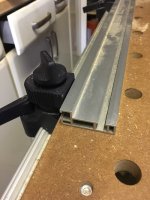
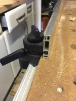
Square up the Factory T-track stops on my MFT3?

gearhound

Member
Joined
Oct 12, 2016
Messages
149
What's the best way to make sure my T-track stops are properly squared? Is there a video I can watch outlining the process?

I'm getting really frustrated trying to get square cuts....I bought a 12" WoodPecker square and I have the back of the rail square to the fence, but still not getting good results. I've watched just about every video I can find for how to square it up and spent hours tweeking it and now figure it has to be that my front t-track stop is not properly placed. Every video I've watched just seems to assume that the stops are perfectly placed from the factory and they don't even address moving them? 

I've got a slop-stop arriving later today and even have that big plywood square from Anderson Plywood arriving tomorrow trying to sort this out. REALLY want to get this thing square and actually start using it!

Thanks for any suggestions.
 
The longer the reference edge you use, the better your accuracy. I started with the 8" woodpecker square and got alright results. Not perfect but much better than it was before I got the MFT. Then got there 18" triangle and noticed a big improvement. The 26" Precision Square I ordered middle of last year is arriving tomorrow, I'll see if that make it better. I don't see how the front stop could cause it to be out. The back of the table to the front is a strait line and you adjust the fence perpendicular to that. The only thing that would make it go out after you square it up would be left to right movement at the front of the table or a bent rail.
 
I've been reading a decent amount of posts of people's 'stops' not being square from the factory. Here's one Gregor posted:

"The factory installed stops inside the slots were off on my new MFT, so using them unchecked as a reference for the rail you might introduce the error you get.

What I did was to setup the back fence, then align the fold-down rail (with the factory-installed stops removed) using a known good square to be rectangular to the fence, then reinstall the stops into the slots at the now known-good position.
Now I can tear apart my MFT for moving and when putting it back together I can align the rail holders against the stops with the confidence of knowing to get a square cut without further checking."

Sounds like the issue I'm having....if it is off it seems to me that when you put the front of the rail onto the tab to register it would pull it just a tad one way or another? I'm not however sure where exactly to relocate the front stop to ensure it is in fact square. Do I just loosen the front stop and slide it until the rail drops exactly on the center of the tab?

EDIT: Maybe it's just having too short of a reference edge, but in the Festool Cabinetry course videos the guy uses the exact square I have so I figure I could get it square. I must be insanely overthinking this, but I square it up with the front rail engaged onto the tab so I see your point of how the front stop isn't causing it to be out?
 
I'm hardly an expert on this process, but have gone through setting it up several times.

The idea is you align the fence to the rail, so as long as the rail is not crazy off mark, then the fence and the rail should be at right angles.  This means the MFT stops (within reason) do not have to be square to the fence off the mark. 

The recommendation, where good right angle cuts are required is that you should calibrate the fence and rail every time you tear down and put back together and even sometimes when you haven't torn it down if you give the fence/rail a whack at some point.  The whole process of calibration should only take 2-3 mins max.

If the tab not being aligned with the front bracket is annoying then there is normally enough slop in the rear bracket to remove that.  If that's not the case then maybe you should move the MFT stops.

I did do this once just to see what needed doing as was I interested.  I used some short Parf dogs and a 24" long, thick straight edge from Veritas to align the rail and brackets to the MFT holes then gently moved the stops to the brackets and locked them down.  Worked for me, but there probably is a better way of doing it.

Mark
 
[member=62622]gearhound[/member]
[member=59661]mleny77[/member]

Your issue is very common, and one that I had initially as well.  Mleny77 is correct regarding the length and precision of the squaring device, which is why some people use qwas dogs.  The issue with using qwas dogs - and I am a major fan of qwas dogs - is the placement of the fence and the guide rail is directly controlled by hole spacing, and don't always jive with where I want them.  So, here goes what I do, and let me add, I'm very happy with the results.

Festool calls the gizzmos that support the guide rail - front and back - "Supports."  The supports come from the factory jammed up against something Festool calls "Feather Keys' locked into place in the bottom channels of the front and back - long - table profiles.  The Feather keys are locked with hex-head set screws which are metric, M8 or M6, I believe.

Loosen the Feather Keys; install the Slop Stop in the Guide Rail; make sure the guide rail is properly secured to the pivot support.  Attach the Festool "Stop Profile" aka the fence to the protractor and position the fence where you want it; lock down the protractor, and install the "Additional Clamp"  at the end of the fence, being sure to lock it down.  The fence should now be fairly rigid.

With the fence in position and the guide rail dropped and in position, place your plywood triangle - Anderson square - with one end firmly against the fence and move your guide rail until it is firmly against the opposing (90 degree) leg of the Anderson Square.

Now move the Feather Key firmly up to the Supports, check for square, and lock down the Feather Keys.  Check to make sure your fence is properly stabilized by the locked down Additional Clamp, and your guide rail is securely locked to the SlopStop by the key of the offside - away from pivot side - Support, and off you go.

Prior to each use I verify square using my Anderson Square or one of my Woodpecker framing squares, whichever is handy.

I hope this helps, and I certainly hope I haven't talked down to you - that of course is not my intention.  For me, once I got the Festool parts nomenclature understood, it was easier to understand what others were talking about.  If you have any further questions, I'll be glad to try and help.

Don
 
Thanks for the detailed response Don! It is greatly appreciated! I can't wait for the Anderson square/slop-stop to arrive and hopefully that will square me up. I'll make sure to come back to this thread and let you guys if I'm able to sort it out.

 
[member=19075]DrD[/member]  Also wanted to ask about doing the 5-cut test once I get in my new square to test out the settings. Is the best way to do it cutting the 1st edge straight without butting it up against the fence and then using that known straight edge up against the fence next and go around the whole piece?

 
One common issue many seem to have is that they square the rail to the fence, but later raise the support brackets for the thickness of material to be cut and find that they are no longer square. Could this be the cause of your problems?
 
It definitely could be [member=182]Corwin[/member]! My woodpecker square doesn't allow me to have the rail raised that much when squaring, so hopefully the Anderson one clears up this issue.
 
[member=62622]gearhound[/member] from my understanding, all cuts for the 5-cut method should be made using the fence and guide rail, but at 72 I may not recollect correctly.  Someone just reposted an older video on understanding how to perform and how to interpret the 5-cut method.  I'm sorry I can't get the reference; it was within the past week and it was on the FOG.  Additionally, someone has included an 5-cut error calculator in a Festool Supplemental manual, and again, I don't recall who, or in which manual.  Wish I could have been of more assistance.

Don
 
No worries [member=19075]DrD[/member]....thanks again for the help! I saw a New Brit workshop video on here of the 5-cut test with some dogs/rail-dogs, but wasn't clear on how to make the 1st cut as he just said to make sure you have a straight edge.
 
gearhound said:
It definitely could be [member=182]Corwin[/member]! My woodpecker square doesn't allow me to have the rail raised that much when squaring, so hopefully the Anderson one clears up this issue.

I'm sure you can find a way to use your square with your material in place -- several methods to arrive at this.

As to the 5-cut test, the first cut in not that important. Rather, it is the following four cuts that tell what's what.
 
1..  The slop stop is critical.  Get that installed first.  Without it there is too much slop for truly square cuts especially wide ones.

2.  Ignore the factory stop on the front of the table.  It is useless, because every time you move up or down for material thickness, you will be out of square for large work.  The height adjustment process has too much slop in it for the factory stop to be of use.

3.  Get the largest square you can find.  I use a Woodpecker's 660mm Precision Framing Square.  Put the short leg on the fence and the long leg a few inches away from the saw track.  Put a shim under the end off the framing square closest to the front so that the leg is level.  Clamp the short leg of the framing square aligned to the fence.  The long leg of the square will be the full length of the saw track.

4.  Adjust the height of the saw track to fit the material you want to cut.

5.  Put a router rail guide on the saw track and adjust it for minimum slop.  Put one of the rods in the rail guide.  Hang a dial test indicator off of the rod and put the plunger so that it rides on the long leg of the framing square.  Zero the indicator at the fence end of the square.  Slide the router guide towards you until you reach the end.  Note the reading and slide back to the fence to make sure it goes back to zero then slide towards you again to make sure the indicated reading repeats. 

6.  Loosen the knob that allows you to slide the front of the track and adjust so the dial indicator reads zero.  Tighten the knob.  Slide the router guide and dial indicator back to the fence and back to you to ensure that the track is now zeroed.  If you are reading less than 0.002 total runout, you are good to go.  It is pretty easy to get under 0.002" total runout across the entire length of the saw track.

This method seems like a lot of steps, but that's just because I had to explain it.  Once you get set up to do it, it is fast and accurate.  No need to do a 5 cut method check.  Cuts will be square even for wide work.  Also, the actual guiding shape of the saw track is used for alignment so it is the most accurate method of alignment.  It also works for any thickness material because the square can always be reached with the dial test indicator.

Once you move the saw track up or down for different material thickness, you will have to repeat.  If I am cutting material that isn't super wide, I will often just square to the framing square and call it good.

In the future, I'm going to make some blocks or angle plates that I can attach to the framing square so that I can reference the front and back of the saw track edge for any thickness of material I will cut.  Right now I can't use the Woodpecker's framing square directly because the long blade would be too low for thicker materials.
 
[member=29691]Hurricane Whisperer[/member]

Love your point #5, and with your permission I a going to coopt for my own use!

Don
 
By all means.  Being a former machine shop owner is both a facilitator and hindrance to woodworking.

It's a facilitator because I am used to doing precision work.  It's a hindrance because I have to stop myself from being more precise than necessary.  That was never a thing with machine work.

In this case, it's a help because my cuts are square with no worry.
 
Corwin said:
One common issue many seem to have is that they square the rail to the fence, but later raise the support brackets for the thickness of material to be cut and find that they are no longer square. Could this be the cause of your problems?

This seems to be the main issue when adjusting the depth.  I have seen a solution, or at least a method that helps, whereby you keep the bracket (the bit that raises and lowers) hard up against the underside of the rail, which you keep flat on the workpiece as you adjust the bracket height.  This helps to keep the bracket square, or vertical.  Any tilting of the bracket as it is raised will throw the guide rail off.  A better solution might be to use parf dogs to square the rail instead of the built-in support brackets.
 
geoffshep said:
Corwin said:
One common issue many seem to have is that they square the rail to the fence, but later raise the support brackets for the thickness of material to be cut and find that they are no longer square. Could this be the cause of your problems?

This seems to be the main issue when adjusting the depth.  I have seen a solution, or at least a method that helps, whereby you keep the bracket (the bit that raises and lowers) hard up against the underside of the rail, which you keep flat on the workpiece as you adjust the bracket height.  This helps to keep the bracket square, or vertical.  Any tilting of the bracket as it is raised will throw the guide rail off.  A better solution might be to use parf dogs to square the rail instead of the built-in support brackets.

Hmmm... I don't see how you can be raising the support bracket while having both the guide rail held flat on top of your workpiece and the bracket held tight to the underside of the guide rail.

I've always just taken care to keep the bracket inline while raising it. I do this by keeping one side of the moveable metal upright indexed against the stationary plastic base while raising or lowering.

Also, if you have squared your guide rail to the fence with the rail flat on top of the table, you can set (clamp) a square on the table with the thin blade pointing up in the air with its edge up tight to the backside of the guide rail. Keep the backside of the guide rail tight to the square as you raise the support bracket. Repeat on other end.

The slop stop looks like a very nice product. I should really invest in one. But, before this was available, we used to recommend that people have the guide rail installed such that the rail would need to be pushed to one side to fit onto the pin on the front support bracket. Skewing the guide rail on the hinged support bracket like this worked fine, and was one of the better tricks that I learned here so long ago.
 
Here's a great video showing the "5 cut method" by William Ng (also building a crosscut sled for the table saw).
Sincerely, Dave.
 
Corwin said:
Hmmm... I don't see how you can be raising the support bracket while having both the guide rail held flat on top of your workpiece and the bracket held tight to the underside of the guide rail.

It does work, you just have to have the rail flat on the workpiece and the bracket hard up against the rail (to keep it square to the rail) before you lock the bracket.

You can also rotate the fence 90 degrees to an upright (tall) position which might allow you to use your square with thicker workpieces.


Attachments

  • IMG_1665.JPG
    IMG_1665.JPG
    69.8 KB · Views: 565
  • IMG_1666.JPG
    IMG_1666.JPG
    65.6 KB · Views: 544
geoffshep said:
Corwin said:
Hmmm... I don't see how you can be raising the support bracket while having both the guide rail held flat on top of your workpiece and the bracket held tight to the underside of the guide rail.

It does work, you just have to have the rail flat on the workpiece and the bracket hard up against the rail (to keep it square to the rail) before you lock the bracket.
I get it now. You are reducing the effect of tilt before locking down.

I think the way I raise and lock sort of does that now but I am going to be extra mindful of that next time and see if it helps.
 
Back
Top