Trestle Dining Table Revisited (completed)

Rounding off the wedged tenons instead of flushing them with the leg really adds an extra bit of depth and character to the table.  Very nice!
 
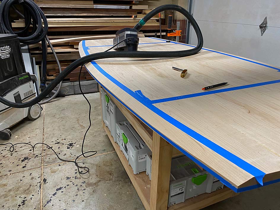
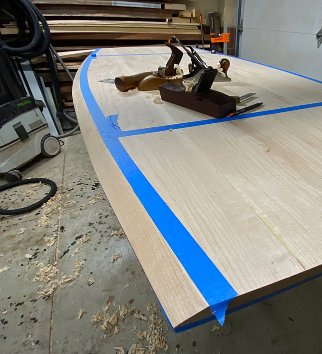
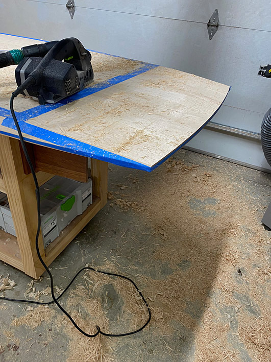
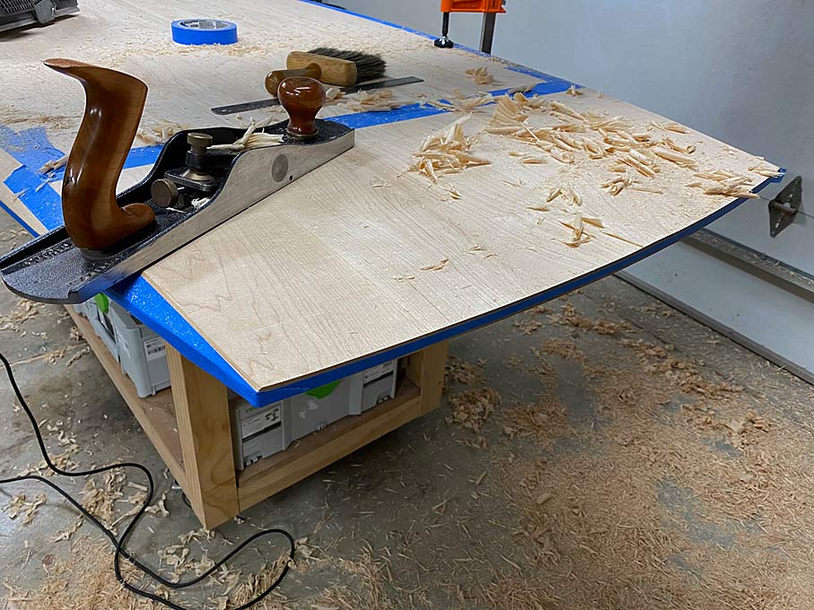
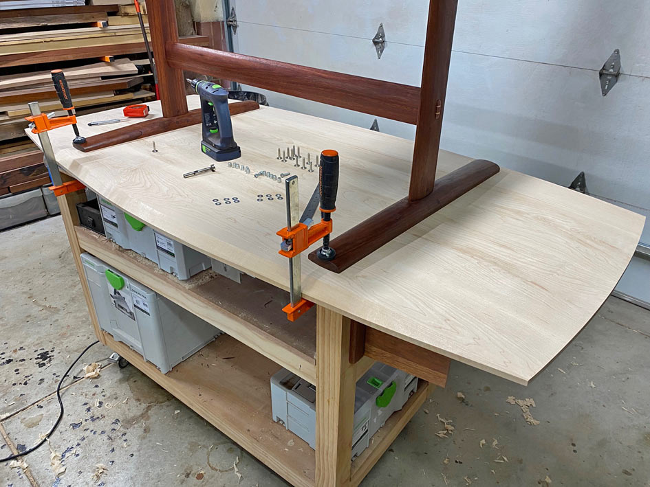
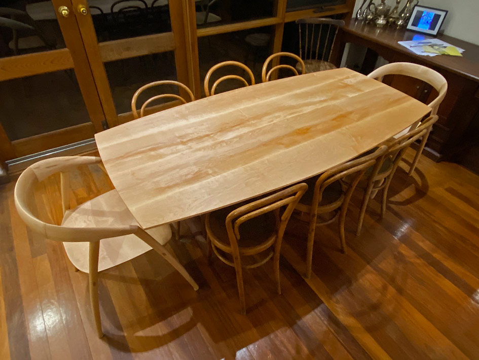
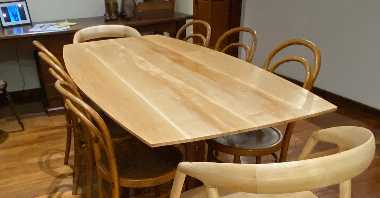
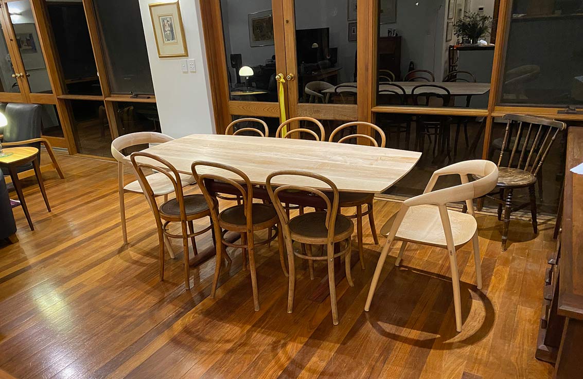
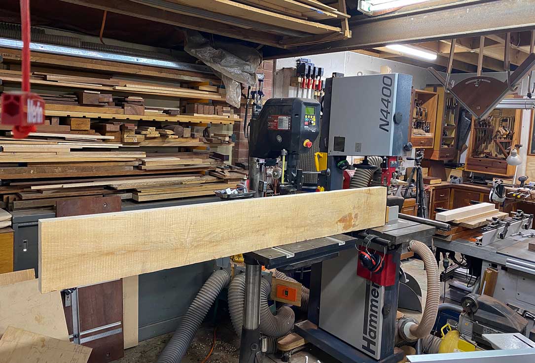
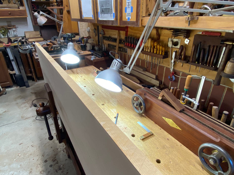
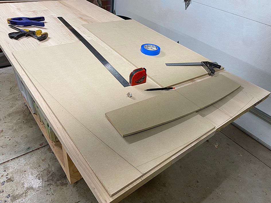
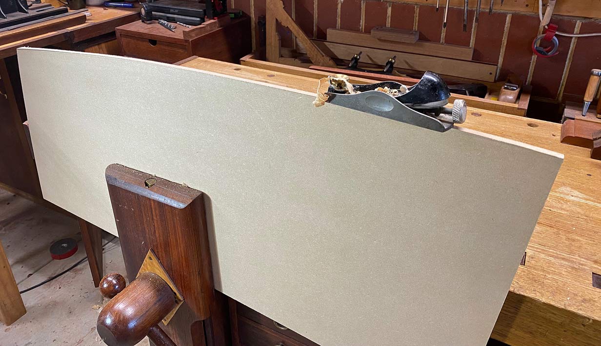
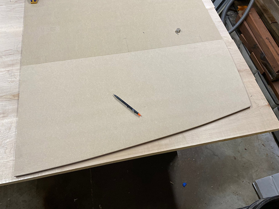
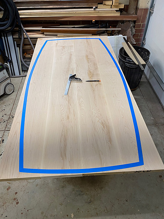
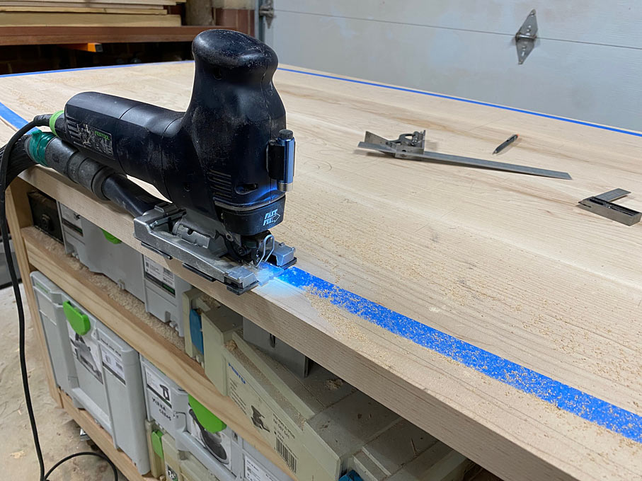
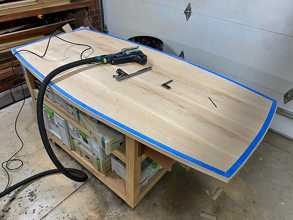
Time to begin the table top. This will end up 1840mm long and 900mm wide, with curved sides.


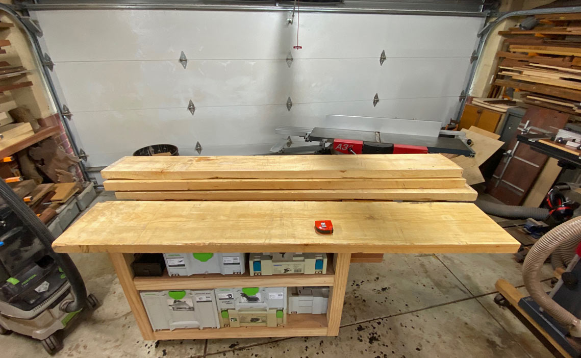
Whoever thought that using machines saved all the grunt work clearly has never built a large table top that started with 2" thick x 10" wide x 6 1/2 feet of Rock Maple! Carrying this around on my own - there is no such thing as "flipping a board" - was a serious workout. Who needs the gym?

One board was just over 12" wide and needed to be cut down to 10". This is too long - and at this stage too heavy - for my slider, and so the ancient track saw came out. Minor issue was the track is short (1400mm) ...


No problem. Just move it down ...


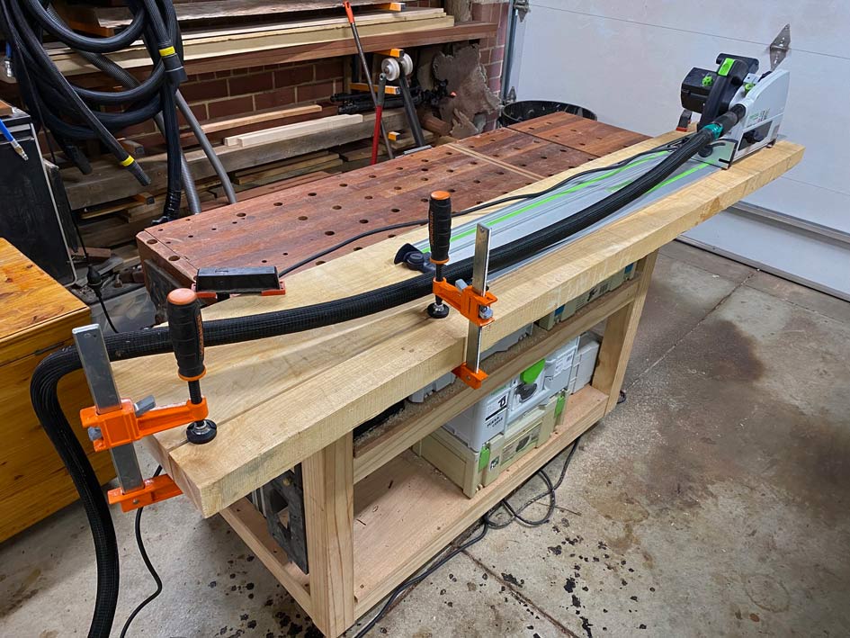
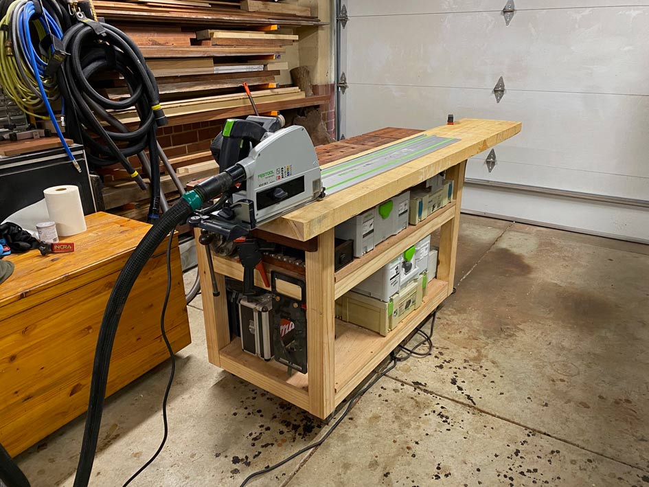
The MFT also works as an in- or outfeed for the jointer and slider ...


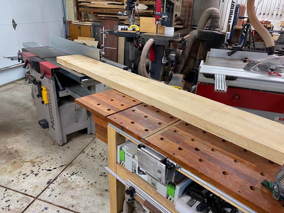
The first two boards I jointed I did in the traditional manner, that is with the hollow side facing down ...


This was a slow and physically exhausting process in spite of the blades set for a deep cut. For the second two boards I flipped them over and ran then over the concave using the fence to balance it on its centre. This was fast! At least twice the speed of hollow-down.

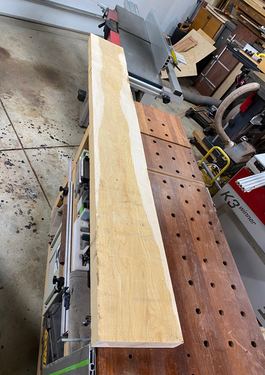
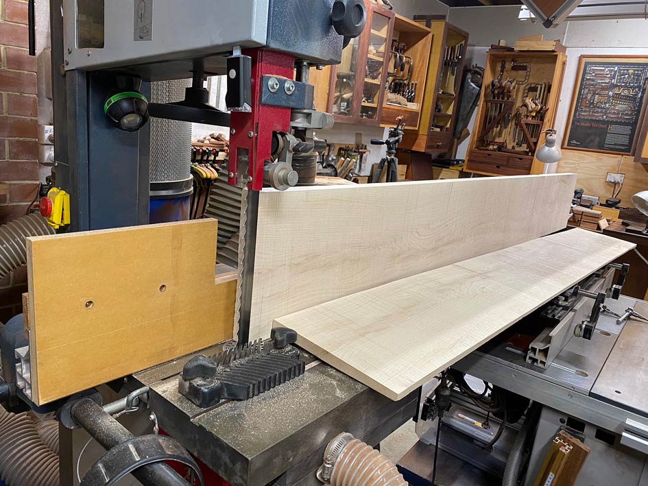
With one jointed side and edge, the boards now needed to be re-sawn to 35mm. The plan was to leave them a little oversize to acclimatise and then thickness to 30mm.

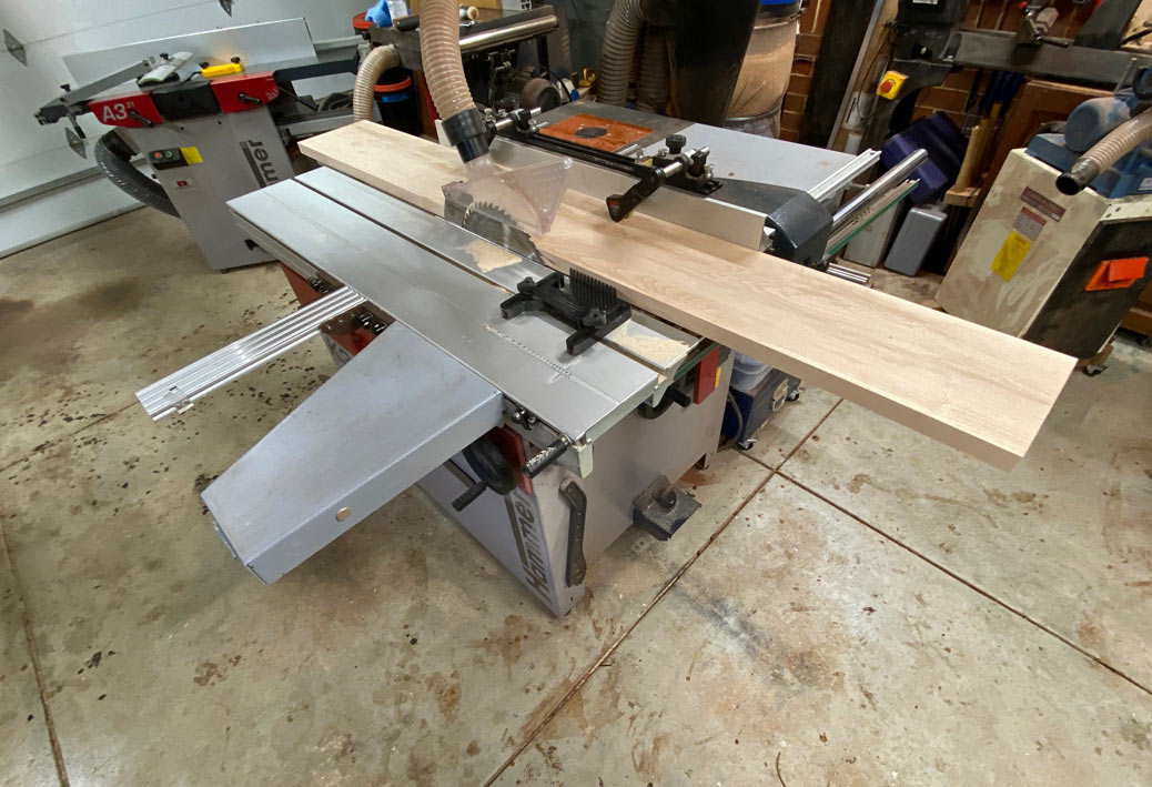
The bandsaw is a Hammer N4400, which is an 18" with a 4 hp motor. Plenty of grunt to drive a 1" carbide Lenox CT Woodmaster blade. But .. running a 1900mm long board on the table is another kettle of fish.

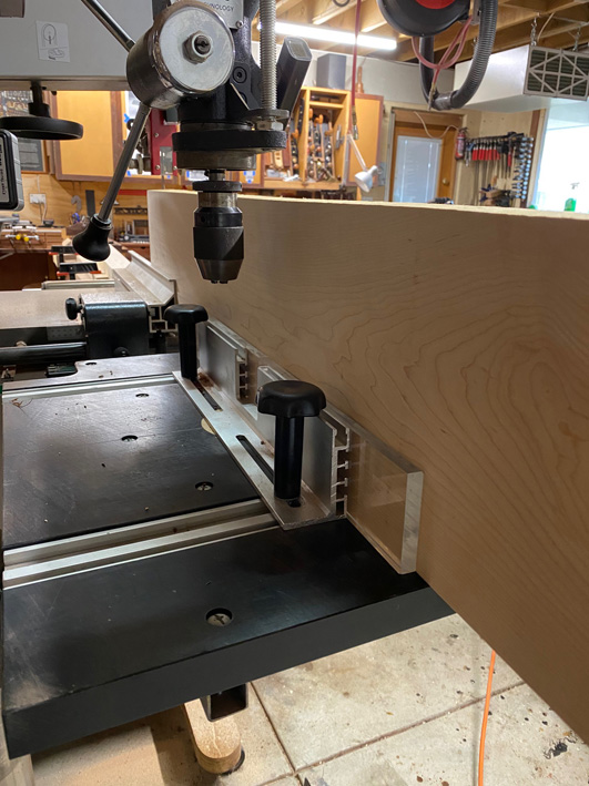
I brought in the drill press table as an infeed, and piled some heavy boards on the slider outfeed as an outfeed ...


The drill press fence made a great guide ...


And the re-saw was as good as I could hope for ...


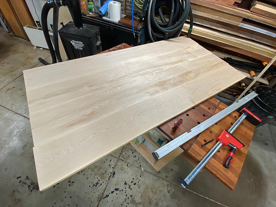
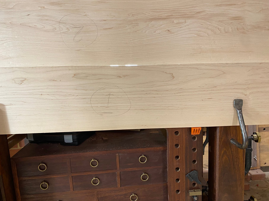
Four boards jointed and thickness planed both sides ...


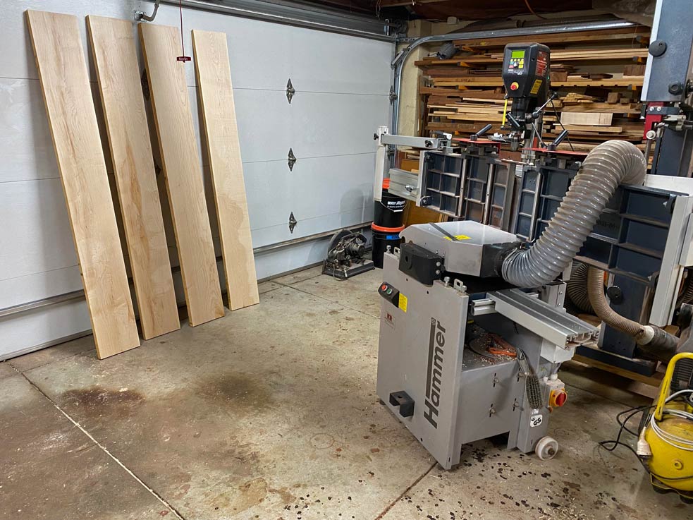
And finally ripped to width ..


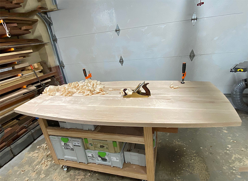
Now we can play at selecting the boards for the top ... try ... flip .. turn ... flip again ... and in the end ...


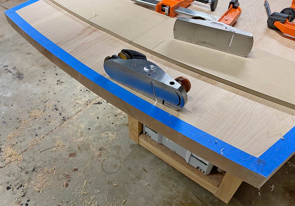
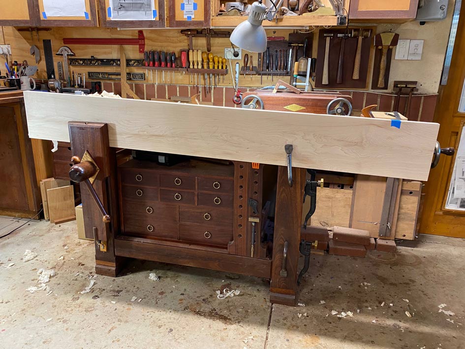
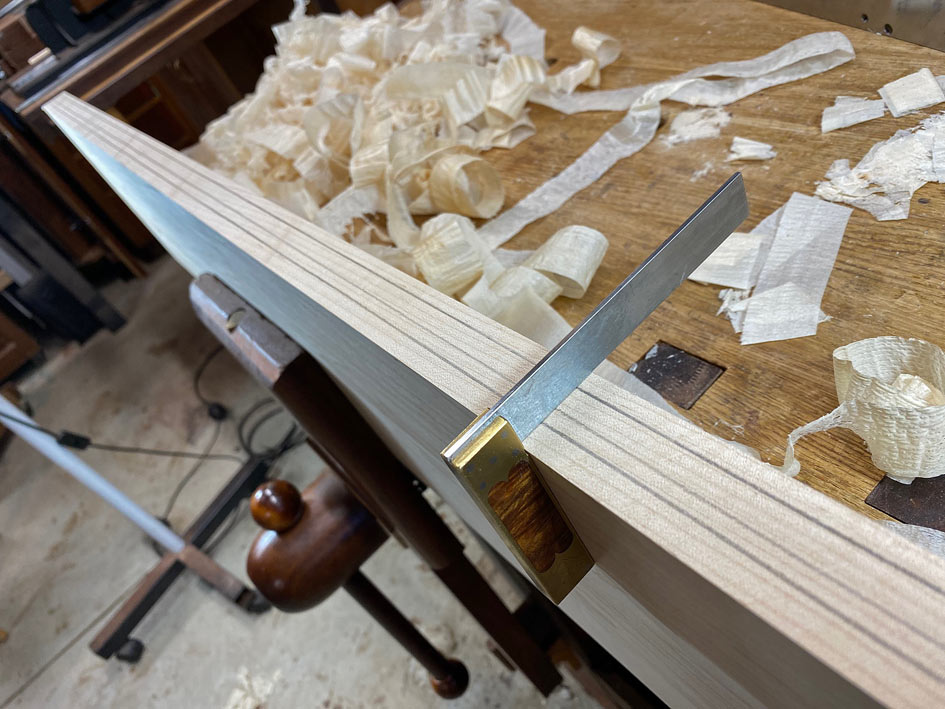
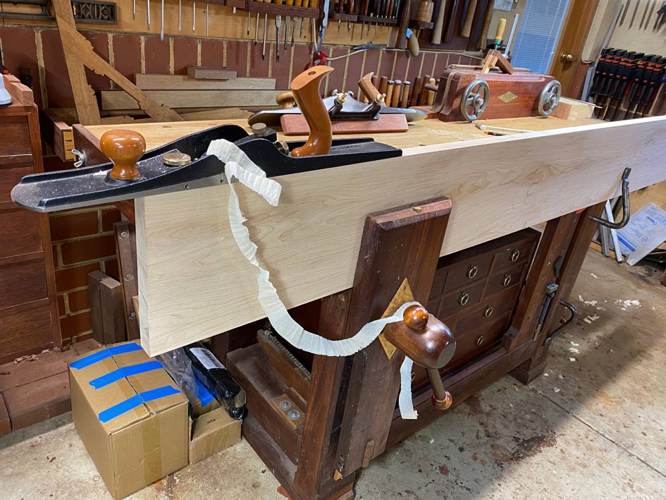
While the boards came off the jointer and slider fairly straight, they needed to be made perfectly straight and square for a gapless joint. This takes place at the bench with a jointer plane ...


What I do is place two adjacent boards together ...


... and shine a light at the rear ...


... to show where the gaps are ...


Remove the high spots.

Next, check the edge for square. This one is angles slightly to the right ..


The strategy now id to move the plane over until only the right side of the blade is cutting. You can see the far side line disappearing ...


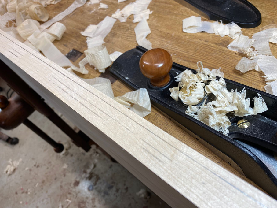
This is the half shaving produced ...


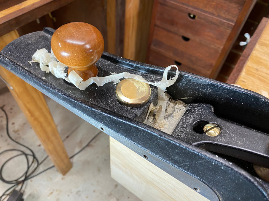
Now that the edge is square, follow this by planing until a full shaving is obtained ...


Finish with a fine shaving ...


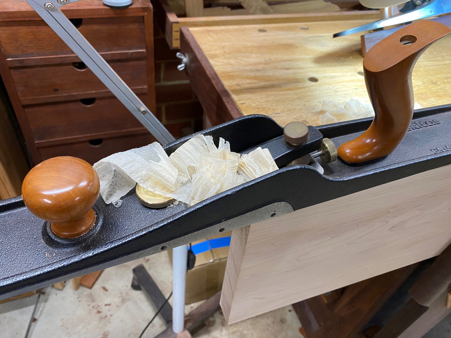
Incidentally, the jointer used here is the Veritas LA Jack. I also have a Veritas Custom #7. Both are excellent. Both get used equally.

The aim is to plane a spring joint - a very fine hollow - at the centre of each board. This will create a gap of around 0.5mm, which can be pulled together with clamp, and serves to avoid the ends of the boards opening up ...


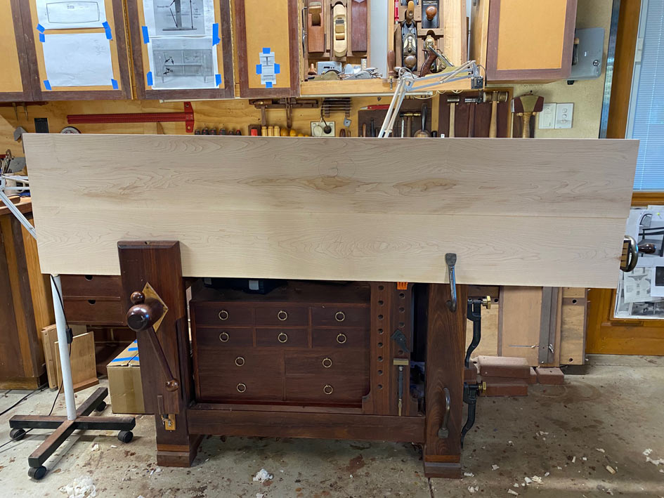
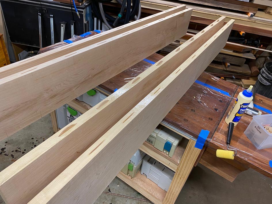
All done, and the next step is to add biscuits to aid in aligning the boards. This is unnecessary for short lengths, but here it aligns the newly jointed tops ...


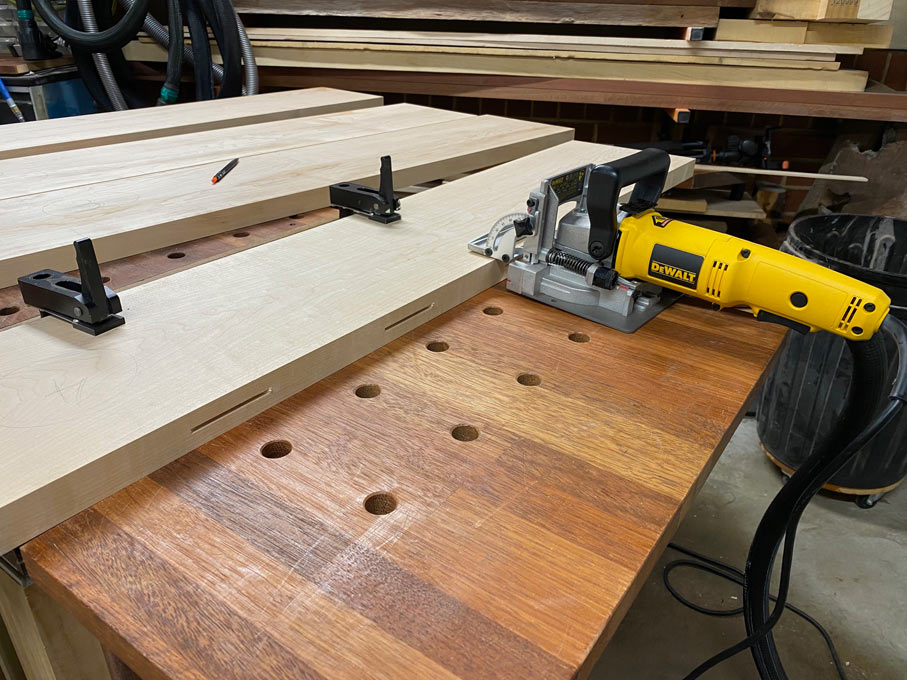
In preparation, the top of the MFT is covered in plastic film ...


Glue rolled on ...


Two board at a time initially ..


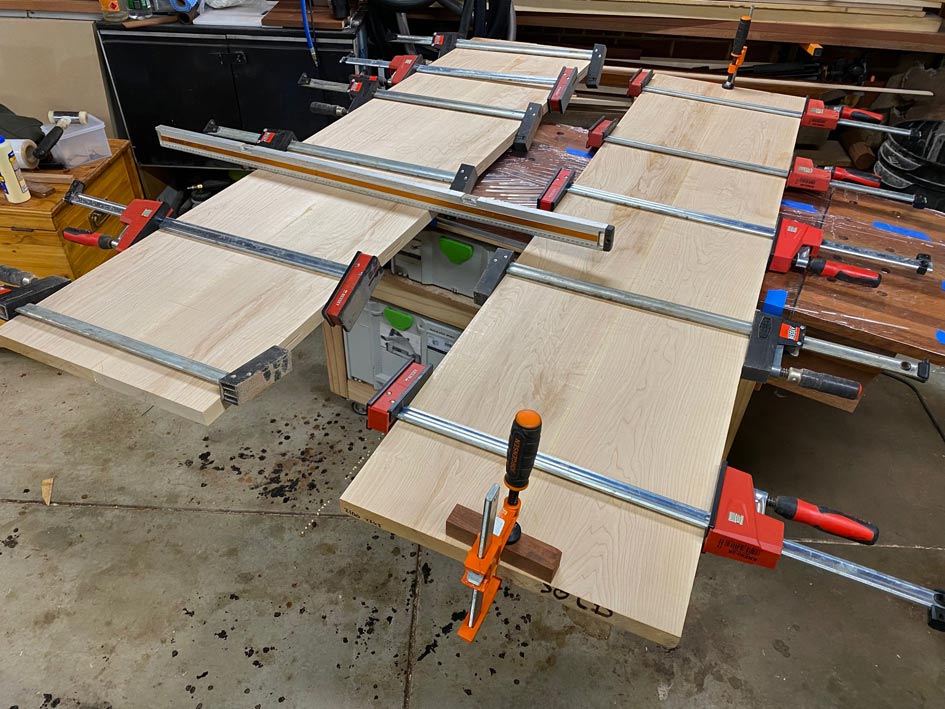
And later joined together ...


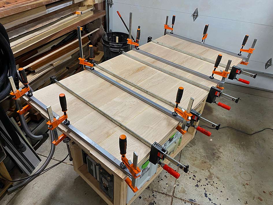
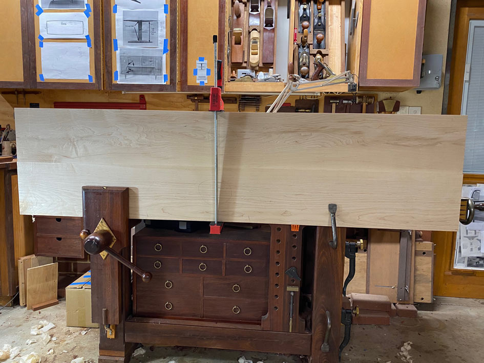
This is where we are at. Back to it next weekend.

Regards from Perth

Derek

 
This is a large post, with many photos, and it takes up to the conclusion of this build. There have been many small details in the design and execution which, when added together, create the final piece. My wife just loves it, and I'm quite pleased myself, so I am happy to share the details for those who are interested in building something similar and with the techniques I used.

With the top glued up, the next step was to mark the outline, which was done by making templates ...


Block plane making shavings of 6mm MDF ...


One quarter used four times ...


Marked out with blue tape for visibility ...


No, I cannot lug this over to the bandsaw. I am not that strong. A jigsaw is used, like a regular person does, cutting close to the line ...


The templates then are used for pattern routing ...


The end grain is smoothed with a block plane. The question is, which works better, a skew block plane or a straight-bladed block plane. Answer: they do the same as one simply holds the straight-bladed plane at an angle :)


The top is pretty flat. The use of biscuits to level the joints worked well. Now the surface is planed with a smoother. This is the finished surface. No sanding was done ...


The side edge is 30mm thick. The plan is to chamfer the edges leaving a 10mm face. This is marked in blue tape ...


The base is positioned on the underside to determine how far in the chamfer will be made ...


A nice, even if rather old, Festool power planer takes away most of the waste in no time at all ...


This is finished to the lines with hand planes ...


The tow ends of the underside are given a long taper, first using the power planer to remove most of the waste ...


.. and then finished with a LA Jack ...


Top done. Time to attach the top to the base.


The plan here is to use bolts into metal inserts, as I do not like the idea of inserting wood screws which might cause splitting and also be vulnerable to being pulled out.


A pilot hole is drilled through the base into the table top to position the bolt holes and inserts.

The holes in the base are made with a 3/4" forstner bit, then drilled for the 6mm bolts using a 7mm twist bit (for a little wiggle room). The hole closest to the leg is fixed while the other two are elongated 2mm each side of the hole for expansion.


Note that the bolt holes go through the base, rather than using wooden buttons as the holes essentially make the attachment invisible from the sides ...


With all attached, the table is done! And two coats of Whittle hard wax oil are rubbed on.

So are we all ready for the unveiling? Drum role ...


The aim of the design was to unite the table with two DC 09 chairs I built. In common are elliptical sections in the table and chairs. The other chairs are vintage bentwood, and the use of curves allows them to be included. The reason for a trestle table, rather than a traditional four-legged table, was to reduce the number of legs with different angles. This is aided by using dark Jarrah for the base, as the base disappears and the Rock Maple top is left as a line connecting the DC 09 chairs.


The curves of the top ...


And a final picture from the kitchen area ...


Thanks all for following along with this adventure.

Regards from Perth

Derek
 
Love everything about this table, Derek! As well as the DC 09 chairs. Fantastic build and really well documented. Might be the final straw to push me over the edge to finally try and build something “furniture”.

Kind regards,
Oliver
 
Both chairs and table are gorgeous, Derek. They go together extremely well. Thank you for allowing us to follow along on your journey. Well done.
 
Beautiful and graceful, Derek!  So well executed!  [smile]  One question, if I may - did you put felt pads under the feet to keep from scratching the floor? 
 
Sparktrician said:
Beautiful and graceful, Derek!  So well executed!  [smile]  One question, if I may - did you put felt pads under the feet to keep from scratching the floor?

Willy, the ends of the base have "crubber" glued to prevent sliding and protect the floors. This is a material made of cork and rubber, and used for gaskets.

Earlier post ...


Regards from Perth

Derek
 
derekcohen said:
Sparktrician said:
Beautiful and graceful, Derek!  So well executed!  [smile]  One question, if I may - did you put felt pads under the feet to keep from scratching the floor?

Willy, the ends of the base have "crubber" glued to prevent sliding and protect the floors. This is a material made of cork and rubber, and used for gaskets.

Regards from Perth

Derek

Great idea!  Thanks for the clarity.  [smile]
 
Some feedbck on the strength and rigidity of the table. This follows a dinner party last night, where guests danced on the table top, used the edges to do push ups, and then proceeded to lean on their elbows while eating.

Okay, so only the last bit is true.

My aim was to build a table with slender proportions. In part, the elliptical shaping created the illusion of slimless, but the dimensions were not over-generous to begin: in the main, mortise-and-tenon joinery 13mm (1/2") thick and 35mm (1 3/8") deep x 70mm (2 3/4") wide in 100mm (4") x 30mm (1 3/16") posts. Most of the (especially USA-made trestle tables) use sections about double these dimensions! I was clearly asking for trouble.

The wood used is in the base is Jarrah and Rock Maple for the top. Jarrah is hard and stiff, but enough? The Maple top looks slim in the photos, but is 30mm thick with edges chamfered to a 10mm edge. That 10mm edge is a repeated theme (also present at the ends of the elliptical stretchers), and comes up again in a short while.


Now there is a part of the build which I have not mentioned. After assembly, there was a slight amount of movement which may be described as the top twisting. It was slight, far less than the trestle table on the patio which I built 25 years ago (which often seats 10-12), dismissed by my wife, but unacceptible to me in my hyper-sensitive state. What I realised was that the width of the uprights was sufficient to prevent downward movement when pressing on the table top edge between the two uprights, but pressing down at the corners forced a slight rotation, and this was experienced as the top twisting. Consequently, I decided to reinforce the top with bracing.

Now here's the dilemma - I did not want to ruin the slimless of the construction with braces which contrasted with the existing lines. I registered what many have done, such as adding angled sections or a rail between the two uprights. I could have added a second elliptical cross rail. I wanted none of that - the cracing needed to be invisible.

Cross bracing: this is in common use in building construction and is strong as it utilises triangulation in its design.  Here is what I did ...

The sections are 10mm thick and 50mm (2") wide. The 10mm thickness was chosen to align with the edge of the upper cross supports.


The ends were dovetailed and glued ...


The cross centre is a lapped joint.

The final construction sits neatly under the table top, and is also screwed at the centre ...


The result is completely invisible from the front of the table. The top of the table is now very rigid and without any appreciable movement at all. Not the slightest! :)

Regards from Perth

Derek
 
Back
Top