Water cooled CNC spindles / Shaper

WillB said:
How's this for timing?
I mentioned a CNC controlled lift and fence system should hit the market, and Next Wave was the logical company to do it... got this email today showing exactly that, a CNC based router table..... impressive, and priced IMO, reasonable considering u have support, parts, etc.
https://www.nextwavecnc.com/shop/SHARK-RS1000-PRO-p470663432

This sort of thing is going to be the way RT's go in the future. I would like to see more detail but I guess it is early days yet. How they power any existing lift should be interesting. We came at this from a different POV which was to keep the cost under a conventional lift & router and give the RT digital capability. I hesitate to call it CNC but it seems that is how it will be marketed.
 
MiniMe....Your goal of making a digital fence / lift system of equal or lower cost than conventional RT fence / lift is impressive.  When you look at the cost of the top end fence systems and lifts, this Next Wave digital fence / lift is not ridiculously priced right out of the gate.  Remember, they go on sale, prices always come out high on initial launch, competitors will surface driving the price lower, etc.  It's obviously not a CNC, but since the company sells CNC machines, I can see why they market it this way.  Its basically a digital fence and depth positioner.  The fence is duplicated with the incra system, and the depth can be achieved with a good lift, which can be controlled to .001" increments. 

IMO, the benefit of digital here is to reduce human error when your cuts require constant movement of the fence and depth of cut such as irregular spaced dovetails, box joints, etc.

For a bit more cost, (considering the added cost of the complete RT system, top, base, dust box, etc.) it seems the SO can do all these tasks plus a lot more.  However, both require the user to do the the physical work, vs. a CNC.  Regardless, its nice to see technology becoming part of small scale ww products. 
 
I totally agree Will, when we started this there was nothing remotely like it for RT's and the cost factor was 90% of our thinking. The fact that we had the ability to make the digital work was cream on the cake. The real back story to our project was me asking Mike my project partner who did the RT I linked to previously if he could write some code for a touch screen digital controller for my Hammer A3-31. Once that was done someone and we can't remember which one of us suggested a router table build. The RT has had fits and starts, Mike did his with a converted Triton to prove the technology and I have had several goes at the spindle version and along the way made a manual one as well. During that time I got roped into developing an automatic blast gate system which is now marketed in Oz but I am no longer involved in that project. The code Mike has developed can easily be used in fence systems such as on a table saw or a bench mounted mitre saw which I might make use of in the future. A cheap version of the Tiger Stop for mitre saws sounds really good to me.
 
It would have been more appealing if this next wave digital router table had a water cooled spindle...

When I think about a digital positioner for the TS, its surely appealing.  However, it can  not have the Incra type design with the long shaft, the length of the travel.  The footprint is often too big for small shops.  The solution would be a rail travel system which seems very feasible with cnc parts.  But unless you are cutting multiple dados or something similar, the applications are more limited vs. RT which cuts end joinery.  There is several DRO fence, which certainly helps, assuming they are accurate.  I have no experience with them, as I use the Incra system. 
 
I have an Incra fence on my mitre saw and I can't say I am in love with it but it is accurate. I am seriously considering selling it and copying what Dennis has done=PLEb0Ut6A7deZj0g0ormBq5_3chFrgr3fp&index=10&t=615s&ab_channel=HookedonWood

My TS rip fence is not a problem, it is a K3 slider and I rarely use the rip fence, perhaps two or three times a year though I did put a Wixey on it because I had it hanging around after I sold my last TS. Jer Schmidt did an interesting fence which is sort of along the lines of Incra thinking and most probably just as accurate, look it up on YT. 
 
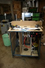
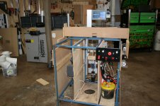
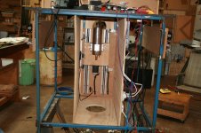
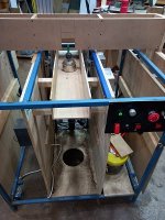
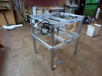
I thought I had better start showing the new table using 20** series extrusion, it was a kit which we cut down from the original dimensions of 1 metre x 1 metre. I am going to have to step through multiple posts with a few pics each time but such is life. I might try and post using designs we have abandoned compared to where we are now. The first shot shows the new table with the old one in the background. The subsequent shots show different views of the old one, actually the old one shown is the third and I never took pics of the first
 

Attachments

  • Whole Table View.jpg
    Whole Table View.jpg
    1 MB · Views: 95
  • Router Table .JPG
    Router Table .JPG
    234.2 KB · Views: 89
  • Router Table View.JPG
    Router Table View.JPG
    629.9 KB · Views: 89
  • RT Side Shot.JPG
    RT Side Shot.JPG
    601 KB · Views: 84
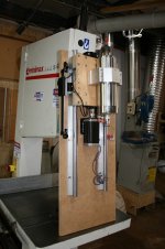
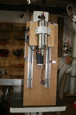
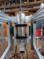
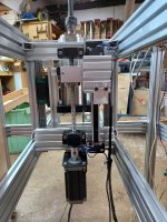
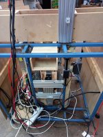
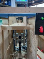
On to the spindle lift, this was the major reason to abandon the blue 20 x 20 RHS table. The reason was because the lift is not attached to the underside of the top it requires a lot of care to get the spindle axis perpendicular to the table top. We weren't far off but it became obvious that getting it spot on was going to be a major mission and the extrusion table seemed to be the obvious way to go as it offered way more flexibility. For instance we can slide the spindle forward or back if the was required and make a top and DE chute to suit the new position with not much effort. I will start off with the new table in these posts followed by the old one for comparison. I am playing with pic sizes to see what works.

Pics 1&2 shows the front and rear view of the current spindle lift & the rest are a series of different versions in the old table.
 

Attachments

  • Version 3 Lift in MDF.JPG
    Version 3 Lift in MDF.JPG
    253.8 KB · Views: 89
  • Version 2 Lift in MDF.JPG
    Version 2 Lift in MDF.JPG
    197.3 KB · Views: 88
  • Spindle Lift Board.JPG
    Spindle Lift Board.JPG
    194.6 KB · Views: 92
  • Rear View of Spindle Lift.jpg
    Rear View of Spindle Lift.jpg
    702.3 KB · Views: 84
  • Front View of Spindle & Lift.jpg
    Front View of Spindle & Lift.jpg
    974.4 KB · Views: 100
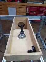
The dust chute in both versions, it draws the air through the table top and in the first version worked perfectly with no debris on the top at all. The insert will have no back to it from the spindle axis line, why commercial tables and insert plates have completely circular insert rings is one of life's mysteries as all they do is make proper dust and debris collection a bit of a nonsense IMHO and through fence collection never works as people hope it will. I am currently thinking an adjustable air entry into the end of the chute might be a good idea but we haven't fired up the latest version to see what happens.


Attachments

  • Dust Cute & Showing Spindle Placement In It.jpg
    Dust Cute & Showing Spindle Placement In It.jpg
    902.9 KB · Views: 91
  • Showing Placement of the Dust Chute.jpg
    Showing Placement of the Dust Chute.jpg
    240 KB · Views: 95
  • Duct Entry End.jpg
    Duct Entry End.jpg
    62.4 KB · Views: 91
  • Duct Exhaust End.jpg
    Duct Exhaust End.jpg
    98.4 KB · Views: 89
  • Duct Through Shot.jpg
    Duct Through Shot.jpg
    50.3 KB · Views: 91
Mini Me said:
On to the spindle lift, this was the major reason to abandon the blue 20 x 20 RHS table. The reason was because the lift is not attached to the underside of the top it requires a lot of care to get the spindle axis perpendicular to the table top. We weren't far off but it became obvious that getting it spot on was going to be a major mission and the extrusion table seemed to be the obvious way to go as it offered way more flexibility. For instance we can slide the spindle forward or back if the was required and make a top and DE chute to suit the new position with not much effort. I will start off with the new table in these posts followed by the old one for comparison. I am playing with pic sizes to see what works.

Pics 1&2 shows the front and rear view of the current spindle lift & the rest are a series of different versions in the old table.
[member=58818]Mini Me[/member] in your first photo, to the right of the ball screw is that a DRO? 

In your second photos showing the spindle mount did you just drill through the 2040 and screw into the 80mm spindle brackets to attach them to the 2040 and then the linear rails or was some thing else done?
 
Back
Top