I had purchased a Shaper Origin when it was introduced at the Festool Connect in Lebanon in 2017, but I never took the time to figure out how to use it. I have also purchased Ron Paulk's Workbench plans (both the originals and the Compact versions), but I do not have a van or pickup truck, so I knew that even the "Compact" one would not fit into my SUV. I recently decided to learn how to use my Shaper Origin along with Fusion 360 to build a SubCompact version of Ron's workbench. After reviewing the plans for the Compact (3' x 6') Workbench, I realized that by reducing the size to 29" x 68" I would need only one sheet of 1/2" plywood, rather than the two sheets specified in the Compact Workbench plans. As the sides require four oval cutouts, and the ends and center require an additional three ovals, I decided to make templates of 1/2" MDF to pattern rout the two different sized oval cutouts, and I decided to design the templates as my first Fusion 360 / Shaper Origin project.
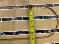
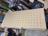
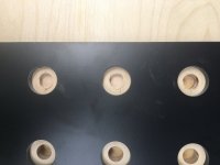
For the top I decided to use 3/4" MDF, rather than 3/4" plywood, as I thought it would result in a flatter, more durable top. I had previously come up with an interesting way to form an MFT-style top (20mm holes on 96mm centers) that I would also like to share here. I start with a slightly oversized piece of MDF. Using my TS55 and a long rail I cut a straight edge along the long dimension. Using a TSO guide I then cut a square corner. Next, I determine the number of rows/columns of 20mm holes that I will be drilling. As the table has a cross support in the middle, it meant that I would need an even number of holes in the long dimension in order to avoid having holes drilled into the center support, so the next step is to convert the finished length (68") of the top to 1727 mm. Dividing that by 96mm tells you that you can have 18 holes (You actually get 17.99 which means 17 holes, plus the start hole). 17 x 96mm = 1632 mm, plus the extra 20 mm, gives you 1652 mm along the length of the top, so that means that you will have (1727 - 1652)/2 = 38 mm to the center of the first hole from the edge. As I thought that 38 mm would be too close to the edge to be of any real use, I added 96 mm to that to get 134 mm to the center of the first hole, while still having an even number of holes, now 16, rather than 18. Similarly, I determined that I could have 7 holes in the shorter (29" dimension) with the first hole being 70 mm from the longer edge. Given that the first 20mm hole will be 134mm from the short edge and 70mm from the long edge, I now placed a mark at that point.
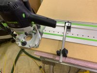
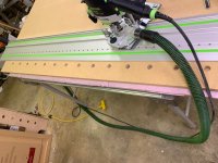
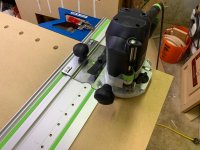
Next, using a long "holey" rail, my OF1400 router with a 20mm bit, the LR32 system, and the TSO square guide, I laid the rail on the top, and I aligned the tip of the 20mm bit with the mark for the first hole. I then slid the TSO guide against the top, and clamped the rail to the top. At that point I proceeded to drill the 16 holes along the top, knowing that they would all be aligned with the long edge of the top. Once the first row of 16 holes had been drilled, I needed to drill the additional six holes in each of the 16 columns. To do that I switched to a shorter "holey" rail. The trick to getting all of the column holes in the correct location is to plunge the 20mm bit through the bottom of the router, and to place it into the first hole that was drilled into the top. Next, place the LR32 plate onto the rail and insure that it snaps into one of the holes. Now slide the TSO guide against the long edge of the top, and clamp it in place. Once you have done that you will be able to complete the top with no further changes in the location of the TSO guide. You can now drill the remaining six holes in the first column. Next, and for the remaining columns, you will plunge the bit, place it into the first hole of the next column, and slide the rail, with the attached TSO guide into position, and drill the remaining holes in each column. Once the top has been completely drilled, it is attached to the base, and a pattern router bit is used to trim the top to the size of the table.
For the top I decided to use 3/4" MDF, rather than 3/4" plywood, as I thought it would result in a flatter, more durable top. I had previously come up with an interesting way to form an MFT-style top (20mm holes on 96mm centers) that I would also like to share here. I start with a slightly oversized piece of MDF. Using my TS55 and a long rail I cut a straight edge along the long dimension. Using a TSO guide I then cut a square corner. Next, I determine the number of rows/columns of 20mm holes that I will be drilling. As the table has a cross support in the middle, it meant that I would need an even number of holes in the long dimension in order to avoid having holes drilled into the center support, so the next step is to convert the finished length (68") of the top to 1727 mm. Dividing that by 96mm tells you that you can have 18 holes (You actually get 17.99 which means 17 holes, plus the start hole). 17 x 96mm = 1632 mm, plus the extra 20 mm, gives you 1652 mm along the length of the top, so that means that you will have (1727 - 1652)/2 = 38 mm to the center of the first hole from the edge. As I thought that 38 mm would be too close to the edge to be of any real use, I added 96 mm to that to get 134 mm to the center of the first hole, while still having an even number of holes, now 16, rather than 18. Similarly, I determined that I could have 7 holes in the shorter (29" dimension) with the first hole being 70 mm from the longer edge. Given that the first 20mm hole will be 134mm from the short edge and 70mm from the long edge, I now placed a mark at that point.
Next, using a long "holey" rail, my OF1400 router with a 20mm bit, the LR32 system, and the TSO square guide, I laid the rail on the top, and I aligned the tip of the 20mm bit with the mark for the first hole. I then slid the TSO guide against the top, and clamped the rail to the top. At that point I proceeded to drill the 16 holes along the top, knowing that they would all be aligned with the long edge of the top. Once the first row of 16 holes had been drilled, I needed to drill the additional six holes in each of the 16 columns. To do that I switched to a shorter "holey" rail. The trick to getting all of the column holes in the correct location is to plunge the 20mm bit through the bottom of the router, and to place it into the first hole that was drilled into the top. Next, place the LR32 plate onto the rail and insure that it snaps into one of the holes. Now slide the TSO guide against the long edge of the top, and clamp it in place. Once you have done that you will be able to complete the top with no further changes in the location of the TSO guide. You can now drill the remaining six holes in the first column. Next, and for the remaining columns, you will plunge the bit, place it into the first hole of the next column, and slide the rail, with the attached TSO guide into position, and drill the remaining holes in each column. Once the top has been completely drilled, it is attached to the base, and a pattern router bit is used to trim the top to the size of the table.