1. Routing a channel for LED lights using the MFS

Cheese

Member
Joined
Jan 16, 2015
Messages
12,501
Some sister threads on LED lighting & a drawer front jig:http://festoolownersgroup.com/member-projects/installing-led-strips-and-other-led-issues/30/
https://www.festoolownersgroup.com/...drawers-for-false-fronts/msg600099/#msg600099

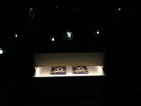
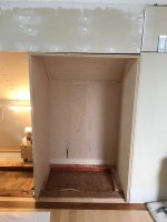
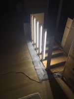
I'm building some cabinets that will be placed in the knee wall of the loft. Each drawer will have LED lights recessed into a stretcher above them. The lighting is controlled with micro switches so they'll activate automatically when the drawers are opened & closed.

The real issue is that because these cabinets will be over 10' long, I need to route out 20 stretchers. That's definitely not a job for clamping and then unclamping the MFS. The stretchers need to be loaded into a fixture, one at a time, indexed, routed, removed and then a new stretcher loaded again. This fixture will also allow each stretcher to be identical to each other and will dramatically speed up the process.

I've used a similar method in the past for producing multiples of HVAC vents and it works really well. The method centers around drilling holes in the MFS  [eek] [eek]  and screwing it to an indexing board. This indexing board will have 2 each 8mm dowels poking out the front and the tie-bars will have corresponding 8mm mortices for the new D8 knock down Dominos. 

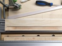
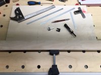
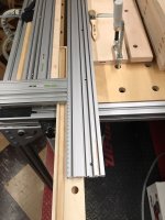
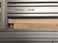
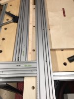
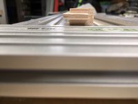
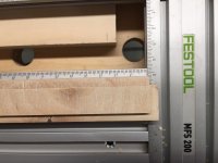
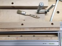
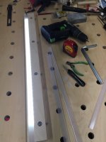
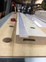
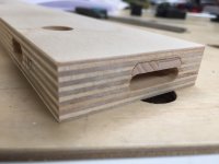
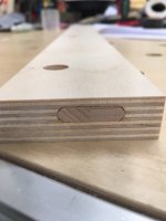
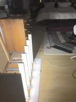
One end of the stretcher will be open while the other end needs to turn 90º to allow the wiring to exit. The width of the slot is critical because a plastic lens will be snapped in place to protect the LED's and to more evenly diffuse the light. The 90º turn also necessitated a wooden spacer be designed & installed in the MFS.

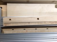
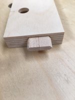
Here's a photo of each end of the stretcher.

[attachimg=1]

[attachimg=2]

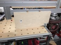
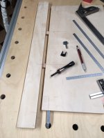
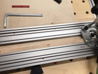
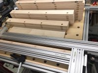
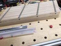
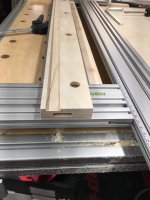
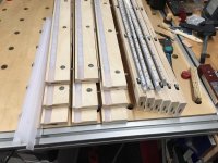
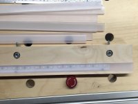
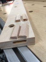
The indexing board is a scrap piece of 18mm BB ply, the same material as the stretchers. It uses 2 Dominos that have had one end smoothed and radiused with sandpaper to more easily engage the tie-bar.

[attachimg=3]

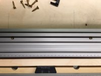
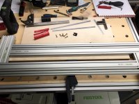
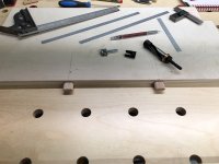
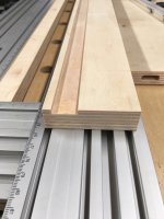
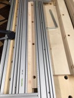
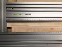
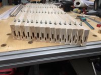
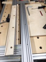
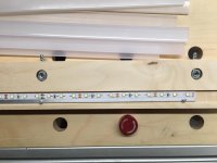
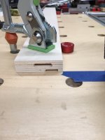
Here the stretcher is being engaged with the indexing board and then clamped in place.

[attachimg=4]

[attachimg=5]

The MFS has been set to the proper size and is placed on the indexing board. I used gauge blocks to properly place the MFS as they are more accurate than pencil lines and faster.

[attachimg=6]

Two #9 GRK screws hold the MFS in place.

[attachimg=7]

Another plus with this setup is that once the MFS is attached, the entire assembly can be moved around and the registration is never lost. If you suddenly need the bench for another job, just pull the assembly and move it.

This shows the underside of the MFS and indexing board because I needed the bench for something else. 

[attachimg=8]
 

Attachments

  • 6752.jpg
    6752.jpg
    222.2 KB · Views: 9,056
  • 6734.JPG
    6734.JPG
    316.6 KB · Views: 8,442
  • 6733.jpg
    6733.jpg
    754.6 KB · Views: 8,490
  • 6732.jpg
    6732.jpg
    972.6 KB · Views: 8,532
  • 6731.jpg
    6731.jpg
    737.7 KB · Views: 8,522
  • 6730.jpg
    6730.jpg
    760.7 KB · Views: 8,563
  • 6728.JPG
    6728.JPG
    789.1 KB · Views: 8,570
  • 6753.JPG
    6753.JPG
    686 KB · Views: 12,213
The 90º turn necessitated that I hang the MFS off of the indexing board. Consequently, I had to fabricate a spacer strip that would allow the 90º turn to be made and that would be captured snuggly within the MFS slot. I again used 18mm BB sliced down to 16mm thickness, the thickness of the MFS, with a dado routed on each side.

[attachimg=1]

[attachimg=2]

The spacer strip is in place on the 90º turn end.

[attachimg=3]

Now's where the fun comes in. The assembly awaits the arrival of the first stretcher.

[attachimg=4]

Each stretcher is loaded from the RH side of the assembly.

[attachimg=5]

Slid into place until the Domino engages with the mortise.

[attachimg=6]

It's then pushed forward to engage the indexing board fully.

[attachimg=7]

The middle clamp is tightened to force everything against the Woodpecker dogs and then the routing begins.

[attachimg=8]

Here's a photo of the slot with the 90º turn.

[attachimg=9]

Once the slot is routed the clamp is released, the stretcher is disengaged and pushed to the right to be unloaded. Pretty simple & pretty quick.

[attachimg=10]
 

Attachments

  • 6771f.JPG
    6771f.JPG
    892.3 KB · Views: 8,257
  • 6771d.jpg
    6771d.jpg
    271.6 KB · Views: 8,217
  • 6771c.jpg
    6771c.jpg
    264 KB · Views: 8,220
  • 6771b.JPG
    6771b.JPG
    786.2 KB · Views: 8,292
  • 6771aa.JPG
    6771aa.JPG
    799.7 KB · Views: 8,448
  • 6771a.JPG
    6771a.JPG
    786.5 KB · Views: 8,313
  • 6771.JPG
    6771.JPG
    362.1 KB · Views: 8,382
  • 6746.jpg
    6746.jpg
    292.7 KB · Views: 8,323
  • 6745.JPG
    6745.JPG
    669 KB · Views: 8,384
  • 6744.jpg
    6744.jpg
    270.1 KB · Views: 8,363
Awesome. Great what led lights are you using? I just recently something like this and i am going to copy it.
 
Here the stretcher has been removed and you can see the completed item with views of both ends. Once set up, the whole process takes only 3-4 minutes for each stretcher.

[attachimg=1]

[attachimg=2]

[attachimg=3]

[attachimg=4]

Now it's time to start attaching the LED's to the stretcher.

[attachimg=5]

[attachimg=6]

[attachimg=7]


Attachments

  • 6824.JPG
    6824.JPG
    436.4 KB · Views: 8,041
  • 6822.JPG
    6822.JPG
    326.1 KB · Views: 8,053
  • 6823.JPG
    6823.JPG
    318.3 KB · Views: 8,049
  • 6777.JPG
    6777.JPG
    261.3 KB · Views: 8,097
  • 6776.JPG
    6776.JPG
    779.2 KB · Views: 8,100
  • 6771h.JPG
    6771h.JPG
    920.6 KB · Views: 8,562
  • 6771g.JPG
    6771g.JPG
    727.6 KB · Views: 8,164
[member=44099]Cheese[/member] 

You are a true MFS Wizard!  Love your setups!  Great work.

Where did you source the plastic channels and the LED strips?  Did the LED's come off a roll?

Thanks, Mike A. 
 
mike_aa said:
[member=44099]Cheese[/member] 

You are a true MFS Wizard!  Love your setups!  Great work.

Where did you source the plastic channels and the LED strips?  Did the LED's come off a roll?

Thanks, Mike A.
Hey Nick, your thread is a "keeper" for reference when I get to the LED strip design and installation in my long wife's long awaited display case.  So I am, like Mike in Cleveland, waiting for more details from you.
The whole approach of fixturing is a vast area of opportunity for woodworking and one newer woodworkers especially benefit from taking a closer look. There's more than power- and hand tools to productive and fun (!) woodworking.

keep it coming!
Hans
 
Hey [member=70360]Slowlearner[/member] and [member=30413]mike_aa[/member]

I usually use Diode LED light strips because I've had really good luck with their products. Their Ultra Blaze product is great for under counter task lighting in kitchens. It's very bright and the color is extremely uniform.

For this project I needed 50' of LEDs which would have cost about $650 including sales tax if I purchased the Diode LED offering.  [eek]

Considering that these LEDs will be on for only minutes in a day because the slides are Blumotion self-closing slides, I decided to cheap out. I purchased 3 each of these 5 meter rolls from Lighting Ever for $36 including shipping.  [big grin]  They use the 2835 SMD device so they're quite bright and they burn at 4100K. The part number is 4100057-DW and they're still rated for 25,000 hours. So that basically equals FOREVER. [big grin]

The covers are from Diode LED and come clear or frosted. They're available in 4' or 8' lengths. A frosted 4 footer costs $8.

The only negative thing about the Lighting Ever LEDs is that the connectors are rather cheap/funky with intermittent connections. I decided to solder the wire leads directly to the LED strip and that solved the problem.

Interestingly enough, I've also had some issues with the Diode LED connectors so I'll be removing those in the kitchen and directly soldering the wire leads to those also.

Here's what they look like when I fired one up last night.

[attachimg=1]
 

Attachments

  • 6842.JPG
    6842.JPG
    230.7 KB · Views: 7,979
TSO Products said:
Hey Nick, your thread is a "keeper" for reference when I get to the LED strip design and installation in my long wife's long awaited display case.  So I am, like Mike in Cleveland, waiting for more details from you.

Thanks Hans... [big grin] ...stay tuned and tonight or tomorrow, I'll post some more photos on installing the LEDs into the stretchers. The covers really make for a very slick installation. They'd look super in a display case. You just have to get the groove width correct because they have short legs and are a friction fit.

You can see how uniform the light pattern is when you install the frosted cover.
 
This is exactly what I want to do with a cabinet for my wife.  Ideally two doors each with a microswitch that can turn on a 20” or so light strip.  Looking forward to more updates!  Thank you!
 
Thanks to everyone for the comments.  [big grin]  I am rather surprised about the amount of interest this post generated.  [cool]

I was originally going to get into the assembly of the LEDs into the stretcher in this thread, but I think I'll start a new thread because there is so much more information I've come across on installing and working with LEDs over the last 15 years.

So wrapping this up, here's a photo of the LE strip LEDs mounted on a heatsink and fastened to the stretcher recess using 4 each #4 screws.

[attachimg=1]

The Diode LED frosted cover is then press fit into place.

[attachimg=2]

Here's an end shot of the cover pressed in-place. You can see the short legs that retain the cover. I machined the slot to .670" +/- .005" by .150" deep. I needed to stay at .150" deep because of the proximity of the 6mm Domino. I'd prefer the slot to be .200" deep instead.

[attachimg=3]

Here are 9 of the 16 stretchers finished. So 16 stretchers plus 4 tops will yield 4 cabinets with 5 drawers each with full illumination.  [big grin]

[attachimg=4]

As I mentioned earlier, the cabinets will be located in a knee wall in the upstairs loft.

[attachimg=5]

Here's a shot of 1 cabinet assembled but without the trim or the drawer fronts.

[attachimg=6]

And here's what the lighting will look like at night.

[attachimg=7]


Attachments

  • 4418_S.JPG
    4418_S.JPG
    89.1 KB · Views: 7,566
  • 4412_S.JPG
    4412_S.JPG
    306.3 KB · Views: 7,607
  • 4229.JPG
    4229.JPG
    439.9 KB · Views: 7,660
  • 6831.JPG
    6831.JPG
    340.6 KB · Views: 7,915
  • 6828.JPG
    6828.JPG
    712.1 KB · Views: 9,352
  • 6827.JPG
    6827.JPG
    227.8 KB · Views: 7,692
  • 6826.JPG
    6826.JPG
    231.7 KB · Views: 7,726
One more item, when doing repetitive work like this it's very important to organize and align all of the products you're working on. Arrange them in order with the proper side up and the proper edges out. Then you can simply take the item, put it in your fixture and perform the work without having to think about it.

Here's a great example of me not following my own instructions.  [doh]

I needed to machine mortises for a 6mm Domino at the +6mm setting. The center of the mortise had to be 10mm from the bottom of the stretcher to avoid interfering with the channel for the LEDs. Here's a photo of the correct orientation. Notice the close proximity to the LED channel.

[attachimg=1]

And this is the result when 1 of the pieces in the stack isn't oriented properly. If I had not caught this and routed the channel, it would have gone right through the 6mm +6mm mortise. I had to slice a couple of 6mm Dominos in half to remedy the problem.

[attachimg=2]

[attachimg=3]

[attachimg=4]

[attachimg=5]


Attachments

  • 6809.JPG
    6809.JPG
    599.1 KB · Views: 7,530
  • 6808.JPG
    6808.JPG
    661.5 KB · Views: 7,624
  • 6807.JPG
    6807.JPG
    720.7 KB · Views: 7,568
  • 6806.JPG
    6806.JPG
    694.1 KB · Views: 7,667
  • 6805.JPG
    6805.JPG
    674.6 KB · Views: 7,609
Nice work on the repair. Going to have to remember that one.

Cheese said:
And this is the result when 1 of the pieces in the stack isn't oriented properly. If I had not caught this and routed the channel, it would have gone right through the 6mm +6mm mortise. I had to slice a couple of 6mm Dominos in half to remedy the problem.
 
[member=44099]Cheese[/member]  - sometimes it pays with smaller, complex set-up parts to make a few extra in anticipation of a machining defect later. Saves the pain of starting another set-up from scratch for a replacement part you hope matches the initial set up dimensions.

My good judgement in these matters comes from my bad experiences in these matters  [sad]

Nick, your "recovery" Domino is a crafty demonstration of your resourcefulness and skill!

Hans
 
So just to add to this thread, you'll remember that in this thread;
http://festoolownersgroup.com/member-projects/installing-led-strips-and-other-led-issues/

I showed an example of what can happen when the LEDs get too hot and the heat is not dissipated properly. Not only does it shorten the LED life dramatically but in this case, it actually burned the silicone cover on the LED.

Here's a photo of 5 stretchers that have been assembled with the LEDs mounted on aluminum flats (heatsinks) and with the plastic Diode LED covers installed. These have been burning continuously for 48 hours. The temp in the room was 67ºF and then I measured the temp of each heatsink end after 48 hours. From L to R 75º.....74º.....74º.....74º.....73º.  I'm very happy with these results. First that's only a worst case 8º temperature rise and secondly the range of temperatures is only 2º.  Aluminum flats work extremely well for distributing the LED heat evenly across a surface.  [cool]

I also measured one of the heatsinks at each end, it was 74º. I then removed the DIODE LED cover and measured the temperature in the middle of the heatsink, it was 75º. That's pretty incredible uniform heat distribution.  [big grin] [big grin]

[attachimg=1]

I mentioned that these are 2835 SMD's @ 4100K. You can see how much light they put out as the embroidery on the pillow shams is visible and that's about 19' away. The 2835's are also very efficient as this is roughly 10' of LED tape and the total draw is .86A or .17A per 2' strip.

[attachimg=2]


Attachments

  • 6921.JPG
    6921.JPG
    235.7 KB · Views: 7,472
  • 6922.JPG
    6922.JPG
    331.9 KB · Views: 7,227
I'm still curious what you plan on doing with the domino connectors in the stretchers.
Apart from that: thanks for the interesting topic.
 
Back
Top