GhostFist
Member
- Joined
- Oct 6, 2010
- Messages
- 1,551
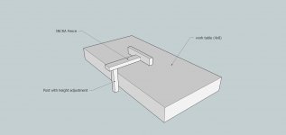
OK I've got a stupid idea for incorporating an INCRA fence with a custom work table (thinking along the lines of a Ron Paulk design). I want the fence to be removable, attached to the side of the table on a height adjustable post (thinking some sort of linear bearing). Height adjustment is to accommodate material thickness. The fence will be used to butt my track saw rail up to so I can use the precision of the incra fence for repeatable rip cuts. It's highly possible that I am stupid and this is a dumb idea, but in my tiny mind it works great. I have no experience using 80/20 or even how to go abouts ordering the right components. Feel free to help and/or yell at me. I'll try and get a rough sketch going.