A kitchen in sunny Eastbourne, UK

andy5405

Member
Joined
May 14, 2011
Messages
407
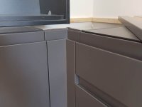
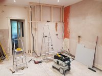
This is my current project which has a few bits of snagging before it's finished. It was installed with a lot of Festools and my TSC55 came in really handy to do the mitred corner posts using a J profile handleless door to match the doors in the rest of the run. It has been a really nice place to work and and a lovely location. It's right in the middle of Eastbourne town centre but the view from the back garden looks like your in the middle of the countryside without a roofline in sight.

It's one of those kitchens where everything came together and you pinch yourself because you actually get paid to do satisfying work in a lovely location for great customers.

[attachimg=1]

[attachimg=2]

[attachimg=3]

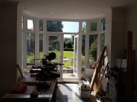
It's hard to believe that this back garden is in a town centre. It's just a fluke that you can't see any rooflines with an unrestricted view to the South Downs.

[attachimg=4]

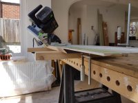
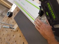
I'm really pleased with how the corner posts came out. It wasn't the easiest cut to do on site but my TSC55, MFT top, some 3x2 and Festool clamps came to the rescue.

[attachimg=5]

More pics here in my portfolio: Handleless Kitchens Eastbourne


Attachments

  • 20170905_171746.jpg
    20170905_171746.jpg
    206.8 KB · Views: 958
  • 20170905_171746.jpg
    20170905_171746.jpg
    206.8 KB · Views: 917
  • 20170905_171859.jpg
    20170905_171859.jpg
    208.5 KB · Views: 927
  • 20170825_142150.jpg
    20170825_142150.jpg
    108.8 KB · Views: 922
  • 20170807_133809.jpg
    20170807_133809.jpg
    51.4 KB · Views: 927
This is how I did the mitre cut. I taped the narrow section of the corner post to another same thickness door. This enabled me to use clamps on the rail and freed up my left hand to apply pressure to the footplate on the TSC55 to stop it tipping. It wouldn't have come out that well without this as the extra battery weight on the TSC is hard to manage on a 45 degree mitre.

Does anyone have any simpler or alternative methods?

[attachimg=1]

[attachimg=2]

[attachimg=3]


Attachments

  • 001.jpg
    001.jpg
    91.6 KB · Views: 911
  • 002.jpg
    002.jpg
    97.4 KB · Views: 890
  • 003.jpg
    003.jpg
    95.4 KB · Views: 881
Nice work  [thumbs up]
I like that you made what tools you had solve the problem.
I would have used my TS55 in the CMS, because I have one, or prior to that with the MFT and guide rail attachment.

Rob.
 
Beautiful kitchen Andy, very nice work.

If I could ask in the first photo behind and to the left is what appears to be a radiator for comfort heating the space. Never come across a radiator of that height here in the States in my 34 years in the trades. Is it hot water, steam, or oil-filled electric? Since I can't see the base in any of the photos or on your website I can't determine which it might be.
 
Bob D. said:
Beautiful kitchen Andy, very nice work.

If I could ask in the first photo behind and to the left is what appears to be a radiator for comfort heating the space. Never come across a radiator of that height here in the States in my 34 years in the trades. Is it hot water, steam, or oil-filled electric? Since I can't see the base in any of the photos or on your website I can't determine which it might be.

It runs off the central heating. There's loads of rads available in this style and size in the UK.
 
Does anyone have any simpler or alternative methods?

Better design. 

We know in advance what size that corner filler is because both elevations start install form that corner.  So, those fillers are mitered/beveled in the factory and then sent to finishing which produces as close to perfect fit and finish as is achievable. 

The installer removes it from the packing and screws it to the two cabinets and moves on the the next cabinet. Nothing to measure, cut, sand glue ect....
 
antss said:
Does anyone have any simpler or alternative methods?

Better design. 

We know in advance what size that corner filler is because both elevations start install form that corner.  So, those fillers are mitered/beveled in the factory and then sent to finishing which produces as close to perfect fit and finish as is achievable. 

The installer removes it from the packing and screws it to the two cabinets and moves on the the next cabinet. Nothing to measure, cut, sand glue ect....
We also have ready made corner posts here, but its more common on the more expensive kitchens that you make custom sizes corners and fillers from doors or drawer fronts

Sent from my ALE-L21 using Tapatalk

 
antss said:
Does anyone have any simpler or alternative methods?

Better design. 

We know in advance what size that corner filler is because both elevations start install form that corner.  So, those fillers are mitered/beveled in the factory and then sent to finishing which produces as close to perfect fit and finish as is achievable. 

The installer removes it from the packing and screws it to the two cabinets and moves on the the next cabinet. Nothing to measure, cut, sand glue ect....

There's a lot of reasons why that wouldn't have worked on this kitchen. I designed it as well as installed it and would always prefer the option of 2 part site cut corner posts on any kitchen.

The biggest reason in most kitchens is that there it's highly unlikely that any corner will be true so any measurements I derive from a plan (where every corner is spot on) wouldn't necessarily work on site. I could trim the gables on base cabinets or pack them out to overcome some of this but it's not an option on wall cabinets. It's also a lot of work and far more than the 2 cuts I had to make on the corner posts.

There is a clearance issue with the set of drawers that opens closest to the American Fridge Freezer. This was best resolved on site and in the end I converted that set of drawers to 400mm deep boxes rather than the standard 450mm. The post still ended up being asymmetric even with all that tweaking.

Part of the wall behind the American freezer has been extended to enable it to fit in that area and again there were unknowns before  the wall was built on site. The gaps either side of the architrave on the door to the left of the American fridge freezer are equal and spot on and again that was best determined on site which affected the final dimensions of the corner posts.

The exact location of the oven tower couldn't be determined as it's proximity to the adjacent door frame was undecided as it depended on overall lighting design in the room. I'd taken the job over from previous contractors who had installed the ceiling lights and we weren't sure what modifications we were going to make to the switching that is adjacent to the oven tower.

I would love to be able to fit factory corner posts but I can't imagine wanting to lose the flexibility of fine tuning corner posts on site. The UK's biggest trade and retail kitchen companies supply single part corner posts at a pre determined size. It's done for the masses so anyone can fit a kitchen but it's not how my part of the market works.   

[attachimg=1]

So I should qualify my question and ask: Are there any simpler methods of doing this on site?
 

Attachments

  • 20170726_114154-01.jpg
    20170726_114154-01.jpg
    86.8 KB · Views: 521
Only as per my original post.
I have had to alter corner posts from the mainstream kitchen suppliers many times (those single MDF foil covered ones you will know only too well)  and it is royal pain in the backside especially when the client was given the option of me designing the kitchen free of charge but went with a company "designer" who had no idea on how plumbing and washing machines work let alone how a kitchen workflow should be organised!
End result was he paid extra for the installation in both labour and materials.
Rob.
 
Back
Top