smorgasbord
Member
Watched some videos of people doing it, and a couple with people explaining it, and decided that my chiseling skills aren't at the level I'd need to achieve the results I want. Re-visiting some v-carve inlay videos, I decided to adapt that strategy. This could be further adapted to the Shaper Origin, too, which would actually be a bit easier, since with that you wouldn't need the mortising template - you could just directly SO rout the mortise into the slab.
Here's the Fusion360 layout for the two pieces: the butterfly itself and the template for cutting mortises:

The key here is to use a shallow angled tapered router bit to both cut a butterfly with angled sides and to cut the matching mortise. Since the mortise and butterfly walls are both tapered to the same angle, insertion/gluing/fit is all but guaranteed.
In case you don't know about V-carve Inlays, here's an image showing a cross-section:
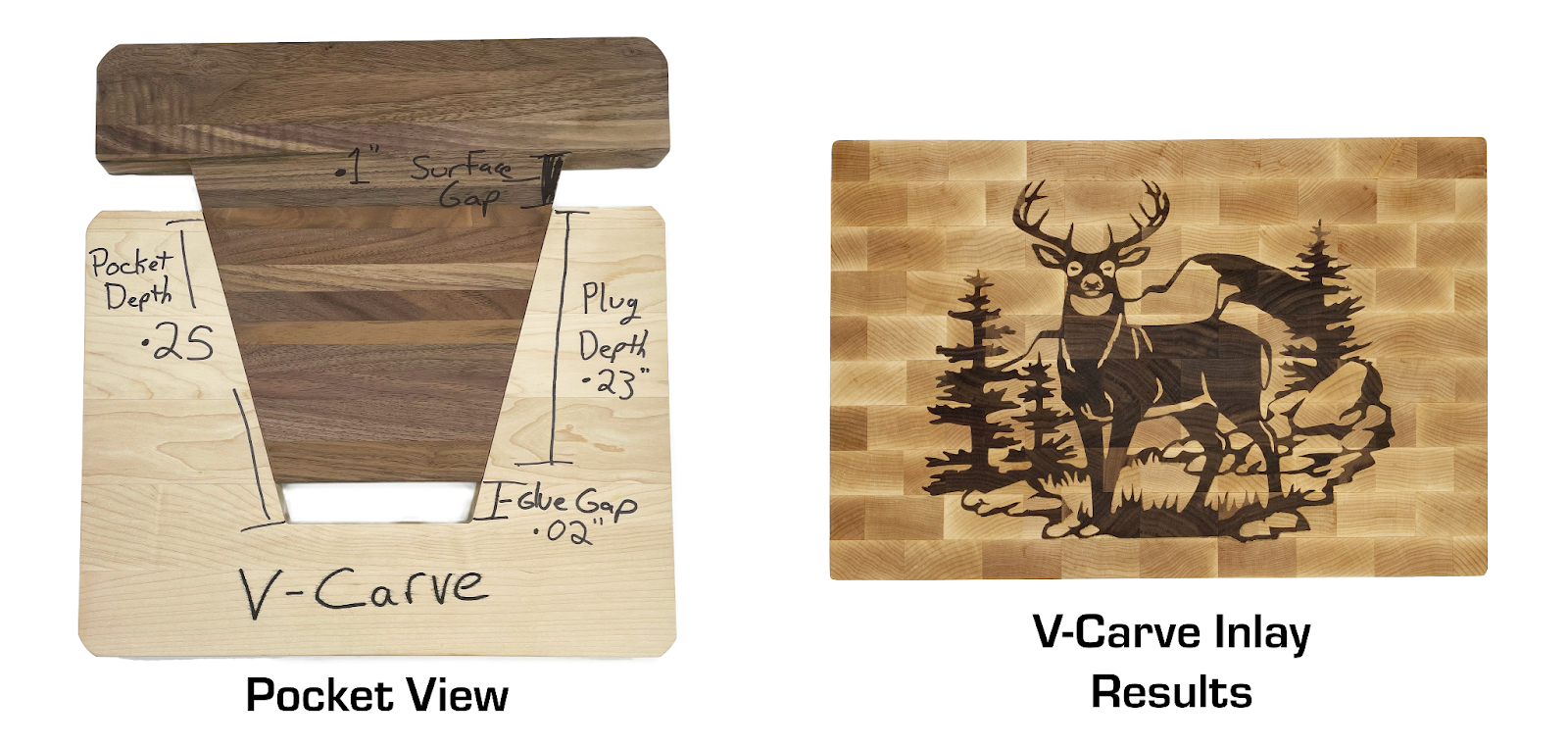
You then plane/sand the inlay to be flush with the top. With the CNC, you typically cut both the mortises and the "plug" on the CNC, then fit and glue, then plane/sand to flush.
Now, these use rather shallow angles, but I'm not sure why. Any inaccuracies in height/depths will change the apparent width/length - and the shallower the angle the more the distortion. So, I started this with a 2.4º bit, and just received a 1º bit that I'll try out tomorrow.
Unfortunately, I built the butterfly in Fusion before creating components, and for some reason once I've done that, I can't seem to put what's built into a component and then create another component in the same file, so I created two files. Any Fusion experts that want to help me out - I'd be much appreciative.
Here are the parameters for the Fusion Files. First the Butterfly itself:

The idea is I built the shape I want to see on the tabletop surface, parameterized by overall length, overall width, and the angle at the outside corners. That gets extruded down into the top as thick as I want, and also up above the table in case the mortise ends up slightly bigger and the butterfly sinks in a bit deeper. The "TaperAngle" needs to be the angle of the final pass bit - easiest to use the same bit in the CNC as in the router cutting the mortise. Since the butterfly is milled upside down on the CNC, it all matches.
And then for the Template:

There's a measurement/calculation that needs to happen plus a bit of math:
1) Depending on the depth of the mortise you want, the tapered bit's diameter at the table top's surface ("BitDiaAtTemplateTop") will vary, but this is just Pythagorean triangle stuff.
2) Depending on the outside diameter of the bushing (What, Smorgasbord is using a router bushing after posting they're dead!?!) you want to use, you need to calculate the offset ("GuideOffset") of how much larger the template has to be to get the mortise size you want.
If everything is cut perfectly, the butterfly will stick up "ProtrusionAboveTop" distance above the tabletop. Note that in this example, the two "Thickness" parameters are not the same, in this case the mortise will be cut 18mm deep but the butterfly will have only 16mm below the tabletop. If the mortise is slightly big, then this 2mm gives some room for the butterfly to sit more deeply without bottoming out. Thinking about this, 2mm is maybe too much, but I'm still doing trials and will cut them open afterwards to see what's going on.
To do this:
1) Put butterfly stock good face down on the CNC bed and cut out the butterfly plug.
2) Cut a straight-sided template.
3) First pass on the mortise uses a ¼" upcut bit with a 7/16" guide bushing with a hand-held router to hog out center waste.
4) Second pass on the mortise uses the tapered bit with a ⅜" guide bushing.
5) Chisel the corners of the mortise by hand.
6) Apply glue to mortise only (don't want plug to swell), insert, and hammer/clamp.
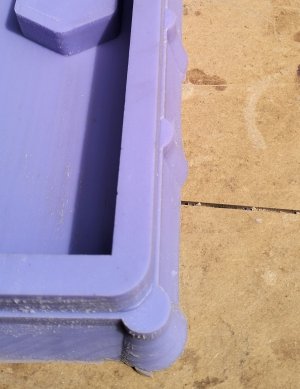
I've done one so far with some scrap and it turned out OK. I'll use the 1º bit next and see how that goes.
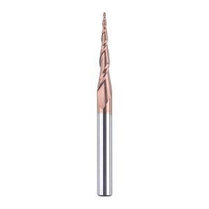
The taper bits are ¼" shank, with a 1/8" diameter bull nose and long enough to get the taper angle right. I actually did order a 0.1º tapered bit but that might be too little taper.
One side question: Why is it that "Vee-Bits" have their angle as the angle between the two cutting edges while the "Taper Bit" have their angles as the angle of the cutting edge from vertical? These are really very similar profiles, so I would have expect the angles to have been measured the same. Took me a long minute to confirm this. IOW, a 90º Vee Bit cuts 45º angled walls while a 2.4º taper bit cuts 2.4º angled walls. Weird.
I'll follow up in the next few days with photos.
Here's the Fusion360 layout for the two pieces: the butterfly itself and the template for cutting mortises:
The key here is to use a shallow angled tapered router bit to both cut a butterfly with angled sides and to cut the matching mortise. Since the mortise and butterfly walls are both tapered to the same angle, insertion/gluing/fit is all but guaranteed.
In case you don't know about V-carve Inlays, here's an image showing a cross-section:
You then plane/sand the inlay to be flush with the top. With the CNC, you typically cut both the mortises and the "plug" on the CNC, then fit and glue, then plane/sand to flush.
Now, these use rather shallow angles, but I'm not sure why. Any inaccuracies in height/depths will change the apparent width/length - and the shallower the angle the more the distortion. So, I started this with a 2.4º bit, and just received a 1º bit that I'll try out tomorrow.
Unfortunately, I built the butterfly in Fusion before creating components, and for some reason once I've done that, I can't seem to put what's built into a component and then create another component in the same file, so I created two files. Any Fusion experts that want to help me out - I'd be much appreciative.
Here are the parameters for the Fusion Files. First the Butterfly itself:
The idea is I built the shape I want to see on the tabletop surface, parameterized by overall length, overall width, and the angle at the outside corners. That gets extruded down into the top as thick as I want, and also up above the table in case the mortise ends up slightly bigger and the butterfly sinks in a bit deeper. The "TaperAngle" needs to be the angle of the final pass bit - easiest to use the same bit in the CNC as in the router cutting the mortise. Since the butterfly is milled upside down on the CNC, it all matches.
And then for the Template:
There's a measurement/calculation that needs to happen plus a bit of math:
1) Depending on the depth of the mortise you want, the tapered bit's diameter at the table top's surface ("BitDiaAtTemplateTop") will vary, but this is just Pythagorean triangle stuff.
2) Depending on the outside diameter of the bushing (What, Smorgasbord is using a router bushing after posting they're dead!?!) you want to use, you need to calculate the offset ("GuideOffset") of how much larger the template has to be to get the mortise size you want.
If everything is cut perfectly, the butterfly will stick up "ProtrusionAboveTop" distance above the tabletop. Note that in this example, the two "Thickness" parameters are not the same, in this case the mortise will be cut 18mm deep but the butterfly will have only 16mm below the tabletop. If the mortise is slightly big, then this 2mm gives some room for the butterfly to sit more deeply without bottoming out. Thinking about this, 2mm is maybe too much, but I'm still doing trials and will cut them open afterwards to see what's going on.
To do this:
1) Put butterfly stock good face down on the CNC bed and cut out the butterfly plug.
2) Cut a straight-sided template.
3) First pass on the mortise uses a ¼" upcut bit with a 7/16" guide bushing with a hand-held router to hog out center waste.
4) Second pass on the mortise uses the tapered bit with a ⅜" guide bushing.
5) Chisel the corners of the mortise by hand.
6) Apply glue to mortise only (don't want plug to swell), insert, and hammer/clamp.
I've done one so far with some scrap and it turned out OK. I'll use the 1º bit next and see how that goes.
The taper bits are ¼" shank, with a 1/8" diameter bull nose and long enough to get the taper angle right. I actually did order a 0.1º tapered bit but that might be too little taper.
One side question: Why is it that "Vee-Bits" have their angle as the angle between the two cutting edges while the "Taper Bit" have their angles as the angle of the cutting edge from vertical? These are really very similar profiles, so I would have expect the angles to have been measured the same. Took me a long minute to confirm this. IOW, a 90º Vee Bit cuts 45º angled walls while a 2.4º taper bit cuts 2.4º angled walls. Weird.
I'll follow up in the next few days with photos.
Last edited: