Hello Together,
After reading in this forum since many years it is time to give something back.
I am using a MFT together wit a MFT VL. I have the CMS modules for the TS 55, the Carvex and for Routers. The problem I had is the height adjustment of the modules in relaion to the spacers of the MFT VL. By adjusting e.g. the TS 55 module the work pieces are stickung at the spacers by changing to the OF module. These duct tape things from Festool for fine adjustment are not very helpful and very expensive.
So a solution was required
View attachment 1
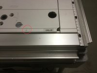
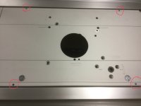
I drilled 4 bores M6, 95mm from the short sides and 5,5mm from the long sides.
View attachment 2
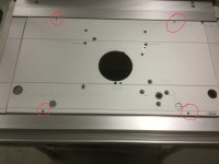
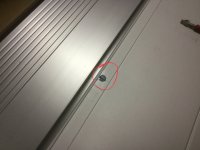
For adjusting the parallelism of the module inside the MFT VL I drilled two further M4 holes in the reception slot.
View attachment 3
View attachment 4
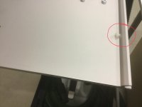
In order to protect the MFT VL I used PA-Screws.
View attachment 5
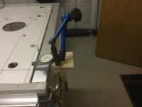
First I adjusted the paralellism to the aluminum profiles of the MFT VL.
After that I adjusted the height of the module to the spacers.
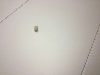
When everything was adjusted, I made M6X5 worm screws with a slot out of a longer cylinder head screw.
View attachment 6
By exchanging the adjusting screws by the worm screws i used Loctite middle strength for fixing.
View attachment 7
After preparing all my modules this way every module is now adjustable individually.
The modules have also a high repeatability of their adjustment after exchange.
View attachment 8
I hope my suggestion will help some other members here.
Best Regards
MMi
After reading in this forum since many years it is time to give something back.
I am using a MFT together wit a MFT VL. I have the CMS modules for the TS 55, the Carvex and for Routers. The problem I had is the height adjustment of the modules in relaion to the spacers of the MFT VL. By adjusting e.g. the TS 55 module the work pieces are stickung at the spacers by changing to the OF module. These duct tape things from Festool for fine adjustment are not very helpful and very expensive.
So a solution was required
View attachment 1
I drilled 4 bores M6, 95mm from the short sides and 5,5mm from the long sides.
View attachment 2
For adjusting the parallelism of the module inside the MFT VL I drilled two further M4 holes in the reception slot.
View attachment 3
View attachment 4
In order to protect the MFT VL I used PA-Screws.
View attachment 5
First I adjusted the paralellism to the aluminum profiles of the MFT VL.
After that I adjusted the height of the module to the spacers.
When everything was adjusted, I made M6X5 worm screws with a slot out of a longer cylinder head screw.
View attachment 6
By exchanging the adjusting screws by the worm screws i used Loctite middle strength for fixing.
View attachment 7
After preparing all my modules this way every module is now adjustable individually.
The modules have also a high repeatability of their adjustment after exchange.
View attachment 8
I hope my suggestion will help some other members here.
Best Regards
MMi
Attachments
-
 49390DE1-475C-48C4-945C-1ABB97055B5E.jpeg590.4 KB · Views: 251
 -
 5065C2B2-C0CE-4E89-BEE8-782D9F65E2A0.jpeg596.3 KB · Views: 216
 -
 A6234C5D-F7E9-47A0-A2CF-21F342AD82D5.jpeg1.6 MB · Views: 222
 -
 3876FB5D-C973-49DE-972E-8E685A3F0260.jpeg493.7 KB · Views: 200
 -
 F2A122EF-CC11-432F-8D5F-46DA13482E71.jpeg2 MB · Views: 214
 -
 B815AB5A-0EE5-40A1-9452-E04DF51E8F8C.jpeg1.7 MB · Views: 179
 -
 F7EA7DA2-3AA6-4427-AA7B-5955DB7503BE.jpeg609.4 KB · Views: 179
 -
 0C924226-1164-40AC-BD9C-B6B3EF0DDE98.jpeg438 KB · Views: 201