AN MFT--My take on it

gibberogill

Member
Joined
Dec 31, 2018
Messages
11
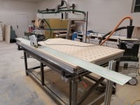
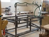
After lurking on this site a while and after gathering ideas on approaches to fabricating my MFT, I finally took the plunge and made my own.  This is what I came up with. [attachimg=1]

I will take you on a tour of this MFT.  Modification suggestions would be much appreciated.

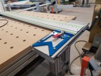
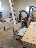
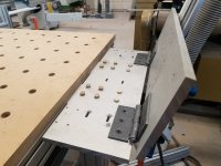
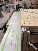
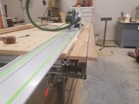
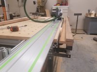
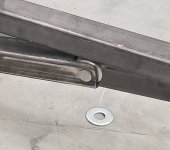
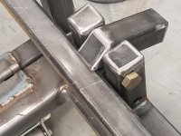
First, there is a cross-cut feature. [attachimg=2][attachimg=3]

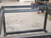
It is on a hinge so it can rotate out of the way if not needed. [attachimg=5]

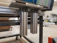
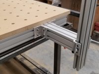
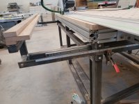
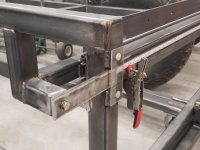
The hinge mechanism is attached to tandem lift bars to allow for differing stock thicknesses.  [attachimg=4]
 

Attachments

  • rsz_mft.jpg
    rsz_mft.jpg
    428.1 KB · Views: 12,829
  • rsz_crosscut_down.jpg
    rsz_crosscut_down.jpg
    351.6 KB · Views: 13,204
  • rsz_crosscut_up.jpg
    rsz_crosscut_up.jpg
    433.2 KB · Views: 13,012
  • rsz_crosscut_elevation_posts.jpg
    rsz_crosscut_elevation_posts.jpg
    307 KB · Views: 12,152
  • rsz_crosscut_hinge.jpg
    rsz_crosscut_hinge.jpg
    369.1 KB · Views: 12,102
What is the piece with the full length hinge to the right of the track saw in the first picture?

What is the boom arm set-up you are using?

Sent from my iPhone using Tapatalk
 
Nice job.  Looks well thought out and solidly fabricated.  One thing though..........are sure it heavy enough ?  [wink]
 
I couldn't get the FOG server to accept my uploads a the office.  Now that I am home, I'll give it another go.

The next items are the indexing posts.  There is one of these situated at each end of the table.  [attachimg=1]

The track rests against the front side of each post.  This allows the track to align with the adjustable rip fence.

Each indexing post can recess out of the way in case the post would get in the way of loading a piece of plywood to the top of the table, or any other reason it would get in the way.  [attachimg=2]
 

Attachments

  • rsz_track.jpg
    rsz_track.jpg
    359.8 KB · Views: 12,494
  • rsz_track_post.jpg
    rsz_track_post.jpg
    288.7 KB · Views: 14,013
The purpose of the full-length hinge?

When the fence is rotated to sit on top of the fence, it acts as a stop for the work piece.  [attachimg=1]

When the fence stop is rotated out of the way if I need an unencumbered surface to help support material with the adjustable fence.  [attachimg=2]

I know it doesn't look like it in these pictures, but the top of the fence and the top of the MFT are at the same level.  It is an optical illusion arising from the table top being longer than the fence.  Also notice the cut groove adjacent to the multi-track.  It is inset 1 inch from the edge.  If the fence is separated from the table, this one-inch ledge allows work pieces to remain supported once they are cut.  [attachimg=3]
 

Attachments

  • rsz_fence.jpg
    rsz_fence.jpg
    371.5 KB · Views: 13,114
  • rsz_fence_stop_down.jpg
    rsz_fence_stop_down.jpg
    326.9 KB · Views: 11,802
  • rsz_fence_stop_up.jpg
    rsz_fence_stop_up.jpg
    335.6 KB · Views: 11,773
[member=69522]gibberogill[/member] - welcome to posting on the FOG and sharing your woodworking and fabricating. You sound like you have an interesting day job in addition to some serious capability in your shop. Keep posting up[dates including some shots of the various features of your MFT being put to work.

Keep it up!
Hans
 
I used a pair of 150 pound capacity 36" drawer slides to attach the fence to the frame. [attachimg=1]

Then, the measuring tape was attached to some 1/4" bar stock which moves when the fence moves.  There is one of these on each end making it so the fence is parallel to the indexing posts.  [attachimg=2]
 

Attachments

  • rsz_drawer_slide.jpg
    rsz_drawer_slide.jpg
    453.7 KB · Views: 11,633
  • rsz_fence_slide.jpg
    rsz_fence_slide.jpg
    327.4 KB · Views: 11,781
Hans, yes my day job entails me acting like a girlie-man most of the day.  I deliver babies and fix broken vaginas.  My shop time is the only time I get to enjoy testosterone. [big grin]
 
The articulating arm overlying the table is from a camera support I used when evaluating abnormal PAP smears in my office.  [scared]  It is made by Ergotron.

Instead of holding a camera, it now organizes a vacume hose and electrical cord out of the way of the work surface.  [attachimg=1]

The entire boom and upright support are removable. 

You can also get a good idea from this picture how the caster elevation system works.  I used this same system on my welding table which weighs upwards of 1500 pounds. 

I can move this table easily by pushing down on the lever--which in turn pushes down the casters thereby lifting up the four legs.  The lever is locked by the simple mechanism shown below.  The lever is unlocked by lifting up the lever catch with my toes.  By so doing, the lever and casters lift up and the table is set down on four legs for a solid base.

Also notice how the shorter lever slides up and down  along the longer lever.  Friction is reduced by using about 10 washers sized for 3/4" bolts.  [attachimg=2]
 

Attachments

  • rsz_boom.jpg
    rsz_boom.jpg
    479.3 KB · Views: 12,081
  • rsz_caster_Washers(1).jpg
    rsz_caster_Washers(1).jpg
    189.6 KB · Views: 11,557
In this picture, the lever is down and locked--meaning the casters are extended and the table is now mobile.  [attachimg=1]
 

Attachments

  • rsz_caster_lock.jpg
    rsz_caster_lock.jpg
    394 KB · Views: 11,650
If i'm reading this correctly you're keep piece is located on the right side of the track as your cutting instead of the traditional left side while cutting?

I understand you can put the keep part on the traditional left side but lose the ability to use the sweet jig you've made.

Also, I'd imagine the term "Pap Smear" was coined by a male dr, no?
 
[member=69522]gibberogill[/member]  - I would not be surprised to see a post from you sometime in the future where you have built a height adjusting worktable which also permits utilization of the storage space beneath.

On your GRS-16 PE attachment method: your picture is the first one I have ever seen where the provided through holes are put to use. We thought they would provide some flexibility for purposes not yet imagined. I had started to wonder whether we should not simply eliminate them since there appeared to be no interest.
I wonder if anyone else has put these extra holes to use ? ?

Keep up the very interesting work!
Hans
 
I felt the TSO Products GRS -16 PE was absolutely essential for this setup.  It allows me to completely remove the track and then re-attach it with a non-drifting zero.  Using the GRS-16 PE instead of the GRS-16 gives me the flexibility to move the cross-cut attachment to the opposite end of the table and rotate the GRS-16 PE 180 degrees and use the same four holes to secure the jig back down to the hinge plates without losing the zero.

To get the most out of the table, I also purchased the MTR-18 Precision System Triangle Set.  By purchasing both products TSO discounted the set heavily.  I can't imagine having an MFT and not using their well thought out products.
 
Beautiful, love it. Looks solidly built and nice attention to detail capping the ends of tube and grinding all the corners smooth. Are you planning to paint it or leave it 'natural'. ;-)

I didn't see any dimensions but looks like you have about 48" crosscut and 96" rip capacity, is that a good guess?

Your mobile base is similar to that on my old table saw. Worked the same way you just stepped on it and the table was lifted up and on wheels in about two seconds, then just push the release with your foot and it's back on the ground solid. Was the best mobile base I ever saw on a contractors table saw. I sold it for a new Unisaw a couple years ago which rarely gets moved but has a mobile base also.
 
TSO----- I did something similar. I used the EZ-ONE Woodworking B300 bridge. Festool + TSO+ B300 bridge..... works a treat. I made bushings that allowed me locating accuracy, repeatably  with the holes you have in the jig. You are right to to think it will be used in in ways that are unanticipated. Due to the high quality of it, this is a good thing. 
 
The dimensions for the top are 97" x 49".  That is all I remember.  The rest of it is on Auto-Cad--which I can post if it is wanted. 

I plan on not painting it until I am finished with building the cabinets for my house.  My wife is an interior designer.  When she asked me what color it was I told her it was standard mill scale.  She told me she thought it was "misty smoke".  Being married to her I have to call a couch--a sofa, curtains--a window treatment, a room in the house--a space.  Life can be so complicated. [dead horse]
 
What I need now is to build cabinets under the MFT to house my growing number of Systainers.  I plan on elevating the bottom of the cabinet an inch or so to allow the caster retract system to function.  I have already framed in the table elevation levers.  I know I can search for systainer cabinets but that can lead to being inundated with pinterest pics, facebook pages, etc. 

Have any of you found systainer cabinets which  might fit with the design of my particular MFT?  Links would be appreciated.
 
[member=69522]gibberogill[/member] Would love to see some pics of your welding table setup! Been looking at making my welding table mobile, but I didn't think a caster lift mechanism like you built would lift a 1000 lbs+ table easily.

Fantastic job on the MFT. I am currently planning and reacquiring materials (8020 and steel just like yours) for my own version of an MFT.
 
Back
Top