bobtskutter said:
I'm loving your work and am looking forward to seeing how this turns out.
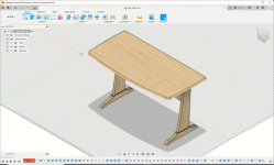
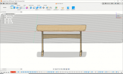
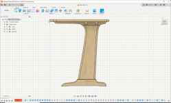
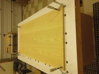
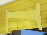
This this going to be a desk for a PC? Could it become a little "tippy", the leg seems to be towards the back of the desk and it looks like it may tip forwards if someone puts too much downwards force on the front edge.
Might the foot at the base of the leg need to be a bit longer?
Thanks for sharing.
Regards
bob
Thank you for the kind words.
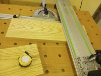
It will house a laptop and two monitors. Funny you mentioned both items. I share the same concerns. There are about 10 iterations of the upright layout. But I settled on this one purely for aesthetic reasons. I feel the weight of the desk will prevent tippiness unless it is stood on or some other extraordinary force is applied. But if not, I'll make changes by redoing the feet and top cleats.